Additional Installation Instructions
B.1 Direct mount
FSS200 clamp-on sensors
Installation Manual, 08/2017, A5E36255466-AC
93
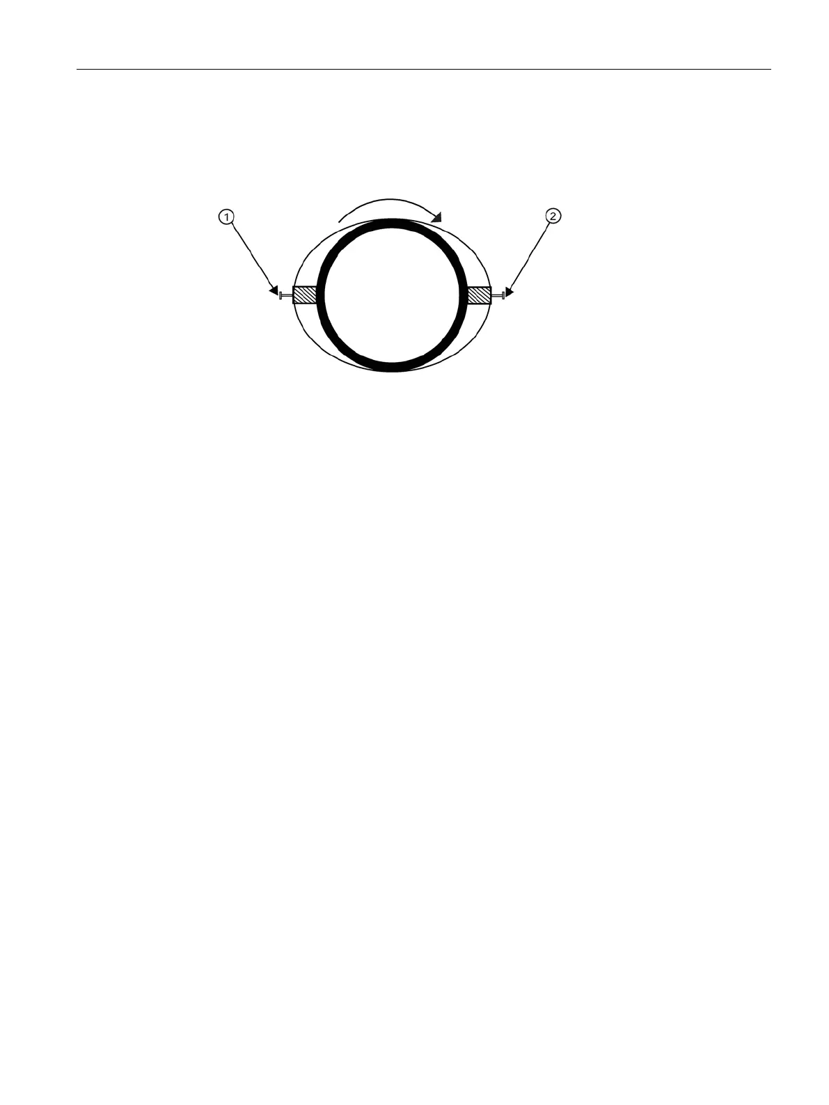
16.Temporarily position the frame (in the 3 o’clock position opposite the mounted frame - see
below) where it will be mounted. Ensure that this is a smooth area without any raised
spots (seams, etc.). Mark a generous area of 13 mm (1/2-inch) all around the mounting
frames with a pencil or chalk. Remove the frame and the Mylar guide.
Figure B-5 Aligning the sensors for Direct Mode operation (end view)
17.Prepare the area you marked by de-greasing the surface, if needed, and removing any
grit, corrosion, rust, loose paint or surface irregularities with the abrasive pipe
conditioning material provided. Clean the pipe of any debris and abrasive particles.
18.Replace the Mylar guide back in the same position it was in and retape it to the pipe
19.Put a mounting strap around the pipe and engage an end into adjusting screw (screw
should be pointing up).
20.Position frame in the middle of area you have cleaned and centered on the pipe with its
angled end facing away from where the other frame will sit and aligned with the edge and
center marks on the guide. Slide the mounting strap over it (and under the clip if there is
one) and tighten with a screwdriver. While tightening, check to ensure that the center of
the tapered roller is centered on the pipe.
21.Take either sensor and apply a continuous lengthwise 3 mm (1/8-inch) bead of coupling
compound across the center of the sensor emitting surface.
22.Tighten the sensor clamping screws to hold the sensor firmly in place.
Repeat procedure
for the other sensor.
23.Slide sensor into the angled mounting frame with the sensor F-connector facing out.
24.Keep sensor from making contact with the pipe until it butts up against the mounting
frame stop. Push sensor down to mate with pipe.
25.Proceed to Sensor wiring (Page 48).

 Loading...


