Connecting
5.2Wiring plan
5.2 Wiring plan
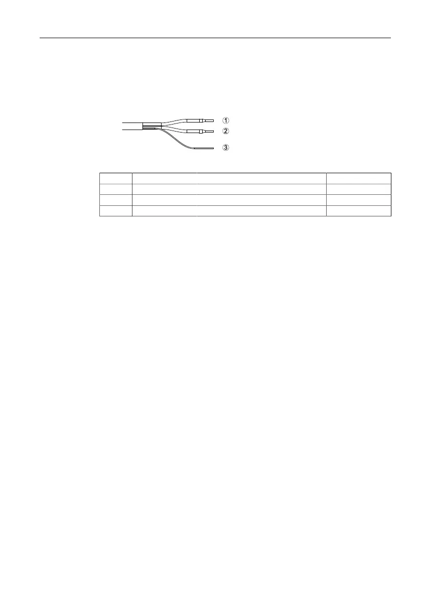
Wire assignment, connection cable
Figure5.1 Wire assignment in permanently connected connection cable
Wire colour Function Polarity
1 Black Voltage supply, signal output Plus (+)
2 White Voltage supply, signal output Minus (-)
3 Shielding
5.3 Switch-on phase
After connection to the power supply, the device carries out a self-test:
• Internal check of the electronics
• Output signal is set to failure
The current measured value is then output on the signal cable.
20
SITRANS LR100
Operating Instructions, 10/2021, 62705-76-01
 Loading...