7ML19985QX81 SITRANS LR250 (HART) – QUICK START MANUAL Page EN-5
mmmmm
English
Installation guidelines
• Provide easy access for viewing the display and programming via the hand programmer.
• Provide an environment suitable to the housing rating and materials of construction.
• Provide a sunshield if the device will be mounted in direct sunlight.
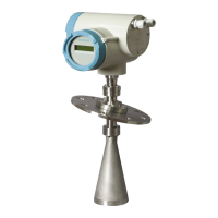
Nozzle design
• The end of the horn must protrude a minimum of
10 mm (0.4”) to avoid false echoes being reflected
from the nozzle.
• An antenna extension: (100 mm / 3.93") is
available.
Nozzle location
• Keep emission cone free of
interference from ladders, pipes,
I-beams or filling streams.
• Make allowance for the emission
code spreading, to avoid
interference with vessel walls or
obstructions. (Beam angle
depends on horn size.)
• Avoid central locations on tall,
narrow vessels, which can
generate false echoes
Note: Beam angle depends on horn
size.
min. clearance:
10 mm (0.4")
beam angle:
1.5" horn = 19°
2" horn = 15°
3" horn = 10°
4" horn = 8°
19°
emission
cone
preferred
undesirable

 Loading...