19
MAN-100411
SITRANS LVL200E - Operating Instructions
55328-EN-170712
2. Loosen compression nut of the cable gland and remove blind
plug
3. Remove approx. 10 cm (4 in) of the cable mantle, strip approx.
1 cm (0.4 in) of insulation from the ends of the individual wires
4. Insert the cable into the sensor through the cable entry
5. Open the terminals with a screwdriver
6. Insert the wire ends into the open terminals according to the wir-
ing plan
7. Tighten the terminals with a screwdriver
8. Check the hold of the wires in the terminals by lightly pulling on
them
9. Tighten the compression nut of the cable entry gland. The seal
ring must completely encircle the cable
10. Screw the housing lid back on
Theelectricalconnectionisnished.
5.3 Wiring plan, single chamber housing
The following illustrations apply to the non-Ex as well as to the Ex-d
version.
5
5
5
5
1 2
4
3
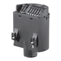
Fig. 10: Material versions, single chamber housing
1 Plastic (not with Ex d)
2 Aluminium
3 Stainless steel (not with Ex d)
4 Stainless steel, electropolished (not with Ex d)
5 Filter element for pressure compensation or blind plug with version IP 66/
IP 68, 1 bar (not with Ex d)
Housing overview
 Loading...