22
MAN-100411SITRANS LVL200E - Operating Instructions
55328-EN-170712
6 Setup
6.1 General information
Theguresinbracketsrefertothefollowingillustrations.
With plastic housings, the switching condition of the electronics can
be checked when the housing cover is closed (control lamp). With the
basicsetting,productswithadensity≥0.7g/cm³(0.025lbs/in³)can
be detected. For products with lower density, the switch must be set
to≥0.5g/cm³(0.018lbs/in³).
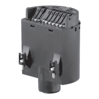
Ontheelectronicsmoduleyouwillndthefollowingdisplayand
adjustment elements:
•
Signal lamp (1)
•
DIL switch for adjustment of the density range (2)
Mode adjustment (A/B)
On the signal conditioning instrument SITRANS SCSC, SITRANS
TCSC, via the signal conditioning instrument.
The switching condition can be changed with the A/B switch. You can
set the required mode according to the "Function table" (A - max. de-
tectionoroverllprotection,B-min.detectionordryrunprotection).
Theswitchingdelaycanalsobemodiedonthesignalconditioning
instrument (SITRANS SCSC, SITRANS TCSC signal conditioning
instruments).
Note:
Always immerse the tuning fork of SITRANS LVL200E in a liquid to
test its function. Do not test the function of SITRANS LVL200E with
your hand. This can damage the sensor.
6.2 Adjustment elements
1
2
1
2
Fig. 14: Oscillator SWE60Z - two-wire output
1 Control lamp (LED)
2 DIL switch for adjustment of the density range
Function/Conguration
 Loading...