Use
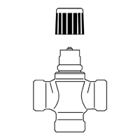
● For 2-way & 3-way 599 Series Zone Valves: 599-00210 - 599-00214, 599-00230 - 599-
00234, 599-00510 - 599-00514, 599-00530 - 599-00534
● Typically in chilled ceiling, VAV and fan coil unit applications
● Max.10 units of SSE161.05U, SSF161.05U can operate in parallel, provided the
controller output suffices.
Technical design
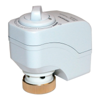
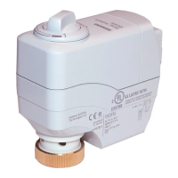
When the actuator is driven by DC 0…10 V positioning signal, it produces a stroke, which is
transmitted to the valve stem.
DC 0...10 V control signal
● The valve opens / closes in proportion to the
control signal at Y.
● At DC 0 V, the SSE161.05U actuator stem is
extended, and the normally open valve is fully
closed.
● At DC 0 V, the SSF161.05U actuator stem is
retracted and the normally open valve is fully open.
● When no power is supplied, the actuator maintains
its current position.
Y = Control signal Y [V]
H = Percentage of calibrated valve stroke
Modulation: Stem retracting
Flashing green in sequence: LED1-->LED2-->LED3 (500 ms each)
Modulation: Stem extending
Flashing green in sequence: LED3-->LED2-->LED1 (500 ms each)
At H0 (fully extended for SSE and fully retracted for SSF) - H40:
Constant green (LED3)
At H40 - H60: Constant green (LED2)
At H60 - H100 (fully retracted for SSE and fully extended for SSF):
Constant green (LED1)
Flashing green (LED2): 100 ms on, 100 ms off
Flashing green/red alternatively (LED2): Green 500 ms, red 500 ms
 Loading...