ST750 GENERAL HANDBOOK
667/HB/33750/000 Page 52 Issue 6
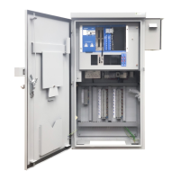
If four or less Detector PCBs are required, sufficient room is available in a Detector
Swing Frame.
The lower portion of the Detector Swing Frame accommodates the Single Detector
Backplanes and Detector PCBs, while a Gemini
2
unit can be mounted on the upper
portion of the Detector Swing Frame.
Figure 14 shows the Detector Swing Frame with, Detectors and Gemini
2
Unit fitted.
Figure 14 – Detector Swing Frame
The Detector swing frame supported in the ST750 is a different part
(667/1/33770/000) to that supported in the ST700.
The detector mounting frame 667/1/27854, as used in the ST700 is
NOT supported in the ST750
If more than four Detector PCBs are required, an 11” Swing Frame will be required
in the cabinet. With the 11” swing frame fitted, the ST750 can support up to a
maximum of eight Detector PCBs and associated Backplanes. With reference to
Figure 15, the 11” Swing Frame must be provided with at least one 11” Detector
Rack Kit. In this case the Gemini unit (if required) is also mounted in the Detector
Rack Kit.

 Loading...


