3.2.2 Troubleshooting
If the extension modules and their positions do not match the values entered in the
basic configuration, or if an extension modules fails during operation, a fault is
generated and handling is stopped. The outputs maintain the state prior to the fault.
No. Name Effect
7101
7102
7103
7104
Fault extension
module
Urgent message; must be acknowledged.
Fault messa
ges
3.3 Free configuration
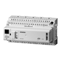
You can freely configure RMS705B within the possibilities of the available function
blocks.
Use the configuration diagram to adjust RMS705B to the plant (see Section 16.2
Configuration diagram").
3.4 Wiring test
Test the wiring after all peripheral devices are connected. We recommend to run
this test after completing the configuration and settings.
Reading values are displayed for the inputs; aggregates (fans, pumps, etc.)
onnected to the outputs can be switched on and off. c
During the wiring test, the appli
cation is inactive, and the outputs are in a defined
OFF state; safety-related functions are deactivated!
The wiring test checks the inputs and outputs for the following types of errors:
Connection errors, i.e. exchanged lines.
Position errors, i.e. mixed up sensor or actuator connections.
Discrepancy between actual type of connection and controller configuration (e.g.
LG-Ni 1000 in place of active DC 0...10 V).
Main menu > Commissioning > Wiring test > Inputs >
Wiring test
Operating line, e.g. Com
ment
N.X1 Display of the current measured value
Main menu > Commissioning > Wiring test > Outputs >
Operating line, e.g.
Positions
Fault relay 1 Off, On
20 / 216
Siemens Switching and monitoring device RMS705B CE1P3124en
Building Technologies Commissioning 01.04.2010

 Loading...


