Technical Description
3-17
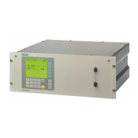
Operating instructions ULTRAMAT 23 gas analyzer
C79000-B5276-C216-03
ULTRAMAT 23, pin assignment (standard)
3.8 Circuit diagrams (electric and gas connections)
37
36
35
34
33
29
30
31
32
18
17
16
14
13
12
11
10
9
8
7
6
5
28
27
26
25
24
4
3
2
1
23
22
21
20
19
15
1
2
3
4
5
6
7
8
9
Note:
Cable and connectors must
be shielded and connected
to chassis potential.
M
M
GND
+5 V
NC
R_level-P-
RD/TD-P
RD/TD-N
NC
R_level-N-
GND
Connector SUB-D 9F (RS 485)
NC
GND
Possibility for connection of
bus terminating resistors to
pins 7 and 9
Relay 8
Relay 6
Relay 4
Relay 2
Analog output N
Analog output N
Analog output N
Analog output N
Connected internally
Contact loading
max. 24 V/1 A, AC/DC;
relay contacts shown:
de-energized relay coil.
Cable and plug must be
shielded and connected
to chassis potential.
N (2, 20, 21)
P 20 Pump On/Off
P 2 CAL input
P 21 Synchron. input
Analog output 4 P (for O
2
)
Analog output 3 P (for IR component 3)
Analog output 2 P (for IR component 2)
Analog output 1 P (for IR component 1)
Relay 7
Relay 5
Relay 3
Relay 1
Connector SUB-D 37F
Safety extra-low voltage
(SELV) with save
electrical isolation.
Safety extra-low voltage
(SELV) with save
electrical isolation.
Inputs
N = 0 V
P = 24 V (external)
M

 Loading...