Operation
5-4
Operating instructions ULTRAMAT 23 gas analyzer
C79000-B5276-C216-03
The number on the right below the display (12345 in this case) is used
as a cross-reference to the summaries of all menus and dialogs which
proceed Sections 5.7 to 5.10 in order to facilitate the locating of the
described display in these overviews.
A reference may be made that the respective function is protected by a
code level (see Section 5.5.1) or is specific to a component.Inthe
case of functions specific to a component, you must enter the
measured components (up to four) for which you wish to call the
respective function (see Section 5.5.2).
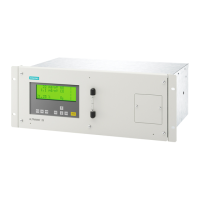
5.2 Display and Input Panel
403.8 vpm CO MF
1875 vpm NO L!
936.4 vpm SO2 RC
4.2%O2PU
MEAS CAL PUMP ESC ENTER
Fig. 5-1 Input panel consisting of display and keypad
The display is a backlit liquid crystal display with four lines with
20 characters each (5 x 8-dot matrix) and is covered by a foil. One line
is reserved for each measured component in the display. The line
displays from left to right: measured value, dimension and name of
component. The last two positions of each line are reserved for
displaying certain analyzer statuses. The meanings are as follows:
S M: Maintenance request
S F: Fault present
S L: Limit violated
S !: Fault logged which is no longer present
S R: Remote control
S C: Function Control (analyzer uncoded, or access via RS485 serial
interface, or AUTOCAL, or in approx. 30 min warm-up mode)
S P: Pump running
S U: Uncoded
 Loading...
