Events and faults 13.4 Messages and troubleshooting measures
Edition 07/2007 Technical Description DTCO 1381 13 - 11
TD00.1381.00 132 102
13.4.1 Overview of the messages
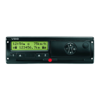
DTCO 1381 display Messages in the display are comprised of the following elements:
(1) Pictograms or pictogram combinations (Picto.)
(2) Additional pictogram in calibration mode (AP)
(3) Error text
(4) Memory code (MC)
Error code The error code can be read-out over the diagnosis interfaces (CAN or
K-Line) with a test device.
Yr" JOUFSOBM
GBVMU
431 2
DTCO 1381 display
Meaning, cause and
measuresPicto. AP
1)
Error text MC
2)
Error code
Operational messages {o --- QSJOUPVUáOPUá
QPTTJCMF
00000005B3 ➥ page 13-14
{o --- QSJOUPVUá
EFMBZFE
00000005B3 ➥ page 13-15
{o --- ESBXFSáPQFO 00000005B3 ➥ page 13-15
{oP --- OPáQBQFS 8000000660 ➥ page 13-15
{j --- FKFDUJPOáOPUá
QPTTJCMF
00000005B3 ➥ page 13-16
{j
{j
--- SFDPSEJOHá
JODPOTJTUFOU
00000005B3 ➥ page 13-16
{j
{j
--- DBSEáFSSPS
00000005B3 ➥ page 13-16
{j
{j
--- XSPOHáDBSEáUZQF
00000005B3 ➥ page 13-17
{jY
{jY
--- DBSEáMPDLFE
00000005B3 ➥ page 13-17
{p --- WJNQVMTFTáXPá
JHOJUJPO
4000000900 ➥ page 13-17
{r --- JOUFSOBMáGBVMU
00000005B3 ➥ page 13-18
{v --- XSPOHáFOUSZ --- --- ➥ page 13-18
{ --- QMFBTFáFOUFS --- --- ➥ page 13-18
Work-time warning messages {d
--- CSFBLá
dI iI
00000005B3 ➥ page 13-19
{d --- CSFBLá
dI iI
00000005B3 ➥ page 13-19
1)
AP = Additional pictogram in calibration mode
2)
MC = Memory code (position in error memory)
 Loading...
