3.3
INSTALLATION OF THE CADENCE MAGNET
ADJUSTING THE POWER MAGNET / TRANSMISSION RANGE OF STS CADENCE TRANSMITTER
?
or
Max. 12 mm
Max. 12 mm
max. 30°
max. 110 cm
Max. 12 mm
Max. 12 mm
3.2
3.2
A
B
STEM OR HANDLEBAR?
INSTALLATION OF THE BRACKET
?
or
1.1 1.2 1.3
?
or
– Remove the
yellow foil
1.4
B
1. INSTALLATION OF THE BRACKET
4.1
7.1
6.1 6.2
4.2 4.3 4.4
2.2 2.3
Max. 90 cm
Max. 30°
INSTALLATION OF THE POWER MAGNETTRANSMISSION RANGE OF STS SPEED TRANSMITTER
MOISTEN ELECTRODES SLIGHTLY WITH WATER OR CARDIO GEL ADJUSTING THE CHEST STRAP
ADJUSTING THE POWER MAGNET
SWITCH FROM BIKE 1 TO BIKE 2 / STS SPEED TRANSMITTER ATTACHING THE ROX 5.0 TO THE WRIST BAND /
HANDLEBAR BRACKET
– In order to achieve the
necessary 12 mm or less
install the transmitter and
the magnet closer to the
wheel hub.
WHEEL SIZE CHART
mm x 3,14
km/h:
WS = mm x 3,14
mph:
WS = mm x 3.14
1x
= WS (mm)
km/h:
WS = mm
mph:
WS = mm
A
B
ETRTO ETRTO
1
6
x
1
.
7
5
x
2
1
6
x
1
.
7
5
x
2
C
47-305
47-406
37-540
47-507
37-584
37-590
40-559
42-559
47-559
50-559
54-559
57-559
57-584
28-630
32-630
40-635
32-622
35-622
37-622
37-622
40-622
42-622
47-622
50-622
54-622
57-622
60-622
23-571
18-622
20-622
23-622
25-622
28-622
1272
1580
1948
1900
2086
2100
2030
2025
2050
2075
2100
2120
2128
2174
2220
2265
2170
2185
2200
2200
2220
2230
2250
2280
2288
2295
2330
1973
2102
2100
2125
2135
2150
16 x 1.90
20 x 1.75
24 x 1
3
/
8
24 x 1.75
26 x 1
3
/
8
, 650 STD
26 x 1
3
/
8
, 650 x 35A
26 x 1.50
26 x 1.60
26 x 1.75
26 x 2.00
26 x 2.10
26 x 2.25
27.5 x 2.25
27 x 1
1
/
4
27 x 1
1
/
4
28 x 1
1
/
2
28 x 1.25, 700 x 32C
28 x 1.35, 700 x 35C
28 x 1.40, 700 x 35C
28 x 1.40, 700 x 37C
28 x 1.50, 700 x 38C
28 x 1.60, 700 x 40C
28 x 1.75
29 x 2.00
29 x 2.10
29 x 2.25
29 x 2.35
650 x 23C
700 x 18C
700 x 20C
700 x 23C
700 x 25C
700 x 28C
kmh
mph
kmh
mph
– Green LED is flashing
– Red LED is flashing
– Green LED = Bike 1
– Red LED = Bike 2– Press > 5 seconds
7. WHEEL SIZE CHART (Choose method A, B or C)
3. INSTALLATION OF THE WIRELESS CADENCE TRANSMITTER
4. ATTACHING THE WIRELESS HEART RATE TRANSMITTER
2. INSTALLATION OF THE WIRELESS SPEED TRANSMITTER
5.1
5.2 5.3 5.4
o
p
e
n
-
c
l
o
s
e
o
p
e
n
-
c
l
o
s
e
o
p
e
n
-
c
l
o
s
e
o
p
e
n
-
c
l
o
s
e
5. BATTERY CHANGE
6. SWITCH BIKE 1 – BIKE 2
o
p
e
n
-
c
l
o
s
e
o
p
e
n
-
c
l
o
s
e
7. WHEEL SIZE CHART
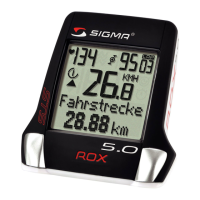
5.0
BIKE COMPUTER WITH HEART RATE
PROGRAMMING EXAMPLES / EXEMPLES DE RÉGLAGE / EJEMPLOS DE AJUSTE
INSTALLATION INSTRUCTIONS / INSTRUCTIONS DE MONTAGE / INSTRUCCIONES DE MONTAJE
CHANGING THE WHEEL SIZE / CIRCONFÉRENCE DE LA ROUE – VÉLO 1 : DE 2155 À 2136 / TAMAÑO DE LA RUEDA BICICLETA 1: DE 2155 A 2136
EXIT SETTINGS / QUITTER LES RÉGLAGES / SALIR DE LOS AJUSTES
Press and hold
for 4 sec.
Press and hold
for 4 sec.
x 1
x 1
x 1x 5
x 2 x 1 x 1 x 2
x 1
SETTING A CUSTOM TRAINING ZONE / ZONES D‘ENTRAÎNEMENT : DE LA ZONE FITNESS À LA ZONE PERSONNALISABLE, LIMITE : 135-160 / ZONA DE ENTRENAMIENTO: DE LA ZONA FITNESS A LA INDIVIDUAL 135-160 LÍMITE
x 8 x 1 x 2 x 1 x 30
x 1
SIGMA-ELEKTRO GmbH
Dr.-Julius-Leber- Straße 15
D-67433 Neustadt /Weinstraße
SIGMA SPORT ASIA
4F, No.192, Zhonggong 2
nd
Rd.,
Xitun Dist., Taichung City 407, Taiwan
SIGMA SPORT USA
3487 Swenson Ave.
St. Charles, IL 60174, U.S.A.
FCC STATEMENT
This device complies with part 15 of the FCC Rules. Operation is subject to the following two
conditions:
(1) This device may not cause harmful interference,
and
(2) this device must accept any interference received, including interference
that may cause undesired operation.
NOTE: This equipment has been tested and found to comply with the limits for a Class B digital
device, pursuant to part 15 of the FCC Rules. These limits are designed to provide reasonable
protection against harmful interference in a residential installation. This equipment generates,
uses and can radiate radio frequency energy and, if not installed and used in accordance with
the instructions, may cause harmful interference to radio communications.
However, there is no guarantee that interference will not occur in a particular installation.
If this equipment does cause harmful interference to radio or television reception, which can
be determined by turning the equipment off and on, the user is encouraged to try to correct
the interference by one or more of the following measures:
– Reorient or relocate the receiving antenna.
– Increase the separation between the equipment and receiver.
– Connect the equipment into an outlet on a circuit different from that to which the receiver
is connected.
– Consult the dealer or an experienced radio/TV technician for help.
Changes or modifications not expressly approved by the party responsible for compliance could
void the user’s authority to operate the equipment.
This device complies with Industry Canada licence-exempt RSS standard(s).
Operation is subject to the following two conditions:
(1) this device may not cause interference,
and
(2) this device must accept any interference, including interference that may cause undesired
operation of the device.
This Class digital apparatus complies with Canadian ICES-003.
o
p
e
n
-
c
l
o
s
e
o
p
e
n
-
c
l
o
s
e
CHANGE BATTERY / BIKE COMPUTER
(BATTERY TYPE CR 2450)
CHANGE BATTERY / SPEED TRANSMITTER
(BATTERY TYPE CR 2032)
CHANGE BATTERY / CADENCE TRANSMITTER
(BATTERY TYPE CR 2032)
CHANGE BATTERY / HEARTRATE TRANSMITTER
(BATTERY TYPE CR 2032)
FIND THE COMPLETE MANUAL,
INSTALLATION AND SETTING VIDEOS
AT: www.sigma-qr.com/rox5
1.4
A
?
or
?
or
2.1
2.4
3.1
?
or
– Remove old battery and wait
1 minute before inserting new
battery
– Remove old battery and wait
1 minute before inserting new
battery
Max. 12 mm
(approx 1/2 inch)
Note – Rubber pad should
touch spoke
Note – 12 mm = approx 1/2 inch
Note – 1“ = 25.44 mmNote – 1“ = 25.44 mm