
V
Valerie HartAug 14, 2025
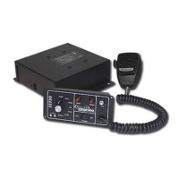
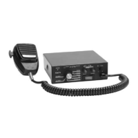
How to troubleshoot no power issue in Signal Vehicle Products Amplifier?
- FFrank PerezAug 14, 2025
If your Signal Vehicle Products Amplifier has no power, start by checking if the power switch is turned on. Then, inspect all connections to ensure they are secure. Also, check the 15A siren fuse and replace it if it's blown. Finally, verify the connection at the power source is tight.