5
Layout
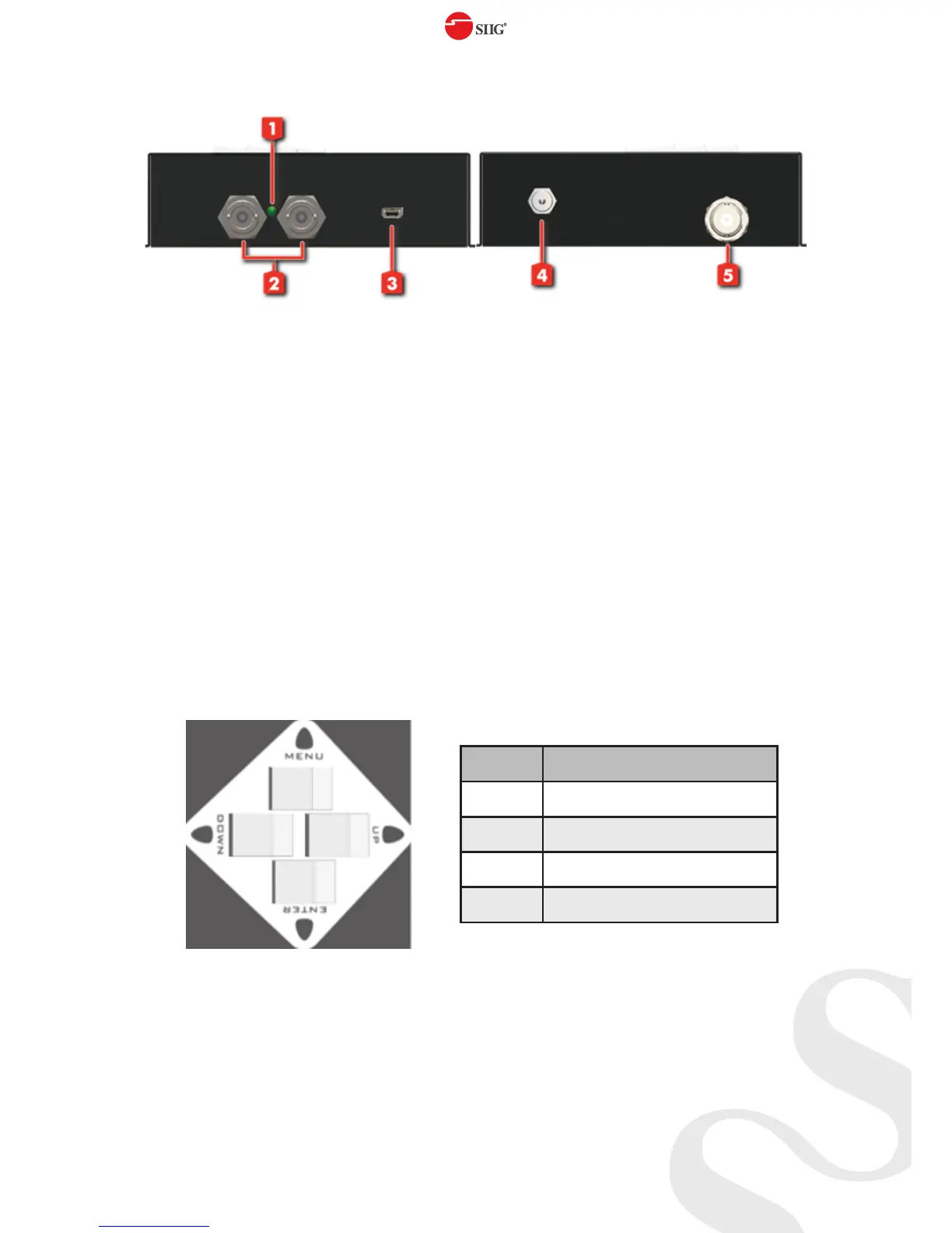
1. Power LED
2. SDI Output:
Connect to a SDI device for SDI signal output either from the
chosen pattern or the SDI source signal
3. Mini USB port: For F/W update
4. Power Input: Connect to a DC 12V power supply unit
5. SDI Input: Connect to a SDI source
PUSH Button
Button Function
Menu Trigger the menu operation
Enter Enter the menu item
Up Choose the last menu item
Down Choose the next menu item