2-64 Trailering Systems
with up to (5) individual trailers. The sensors must be
mounted onto each tire and wheel assembly, and the
sensors must be learned by the vehicle by following the
learning procedure as shown in the Trailering App
section of this manual. For sensor installation
assistance, please contact your trailer service center or
tire service center. The Trailer Tire Pressure Monitor
System sensors monitor the air pressure in the trailer
tires and transmit the trailer tire pressure readings to a
receiver located in the vehicle. The trailer tire pressure
sensors can transmit up to 23 feet (7 meters) from the
hitch receiver of the vehicle. The tire pressure values
can be viewed in the trailering app in the vehicle’s
center stack.
Trailering Diagnostic Tools
In some situations when diagnosing trailer tire pressure
monitoring, trailer lighting, or integrated trailer brakes, it
may be necessary to connect the vehicle to a trailer to
confirm proper operation. Performing this activity may
prove difficult in the service environment since trailers
are not often available for diagnostic use, may have
existing electrical issues outside of the issues a
technician is attempting to diagnose, or simply may be
too unwieldily to connect for diagnosis.
With all this in mind, it may be helpful to build or create
a tool that can be plugged into the vehicle’s trailer
connector and simulate a connected trailer. This tool
would include park lamps, stop lamps, and a reverse
lamp for lighting and trailer tire pressure monitoring
diagnosis. It can be expanded to include trailer brake
magnets to diagnose integrated trailer brake concerns.
Also, an additional lamp can be included to diagnose
the B+ circuit to the trailer.
Trailer issues are NOT covered under warranty, but
these tools may be used to verify the vehicle is
functioning properly and to help the customer
understand and correct any trailer related issues if they
so choose.
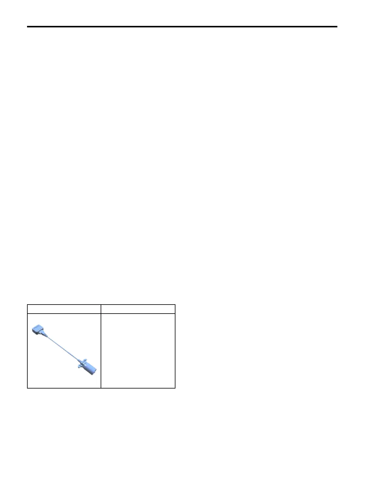
Available Trailer Presence
Simulator Tool
Illustration Tool Number/Description
5166189
EL-52641
Trailer Presence
Simulator Tool
Simulated Trailer Lighting
Creating a tool to simulate a connected trailer can be
used to diagnose issues with trailer lighting, trailer
brake (if equipped), the Trailering App (if equipped),
and trailer tire pressure monitoring system (if
equipped).
If the vehicle is equipped with a K68 Trailer Lamp
Control Module (U1D/UET), the module monitors the
current on the lighting circuits to determine a trailer has
been connected. The Trailer Lamp Control Module
pulses current on the trailer lighting circuits every
42 minutes to monitor for a connected trailer. If a
current draw greater than 55mA is detected, the Trailer
Lamp Control Module recognizes this as a connected
trailer. This will enable any trailer lighting controlled by
the Trailer Lamp Control Module. The Center Stack
Module will also use this trailer detection as a cue to
enable the Trailering App and trailer tire pressure
monitoring functions.
Creating a Simulated Trailer Lighting Tool
Parts needed:
• 7-way RV trailer connector Qty: 1
Note: The combination trailer stop/turn, and
backup lamps must draw at least 55mA of total
current to be detected as a trailer. Some LED
combination lamps will not draw enough current.
If an LED combination lamp is used, make sure it
draws at least 55mA. A load resistor can be added
to the circuit if necessary to obtain the correct load.
• Combination trailer park/stop/turn lamp (greater
than 55mA drawn when on) Qty: 2
• Reverse lamp Qty: 1
• 12 gauge wire and terminals/connectors Qty: As
needed
• 18 gauge wire and terminals/connectors Qty: As
needed
• Mounting board Qty: 1
1. Connect a 12 gauge wire to the ground terminal of
the 7-way trailer connector and the ground circuit
of each combination trailer park/stop/tu rn lamp and
the reverse lamp in parallel.
2. Connect an 18 gauge wire between the park lamp
terminal of the 7-way trailer connector and the park
lamp circuit of each combination trailer park/stop/
turn lamp in parallel.
3. Connect an 18 gauge wire between the left turn/
stop lamp terminal of the 7-way trailer connector
and the turn/stop lamp circuit of left trailer park/
stop/turn lamp.
4. Connect an 18 gauge wire between the right turn/
stop lamp terminal of the 7-way trailer connector
and the turn/stop lamp circuit of right trailer park/
stop/turn lamp.
5. Connect an 18 gauge wire between the reverse
lamp terminal of the 7-way trailer connector and
the reverse lamp.
Note: A combination trailer lighting and trailer
brake tool can be created on the same mounting
board.
6. Mount the left combination trailer park/stop/ turn
lamp, right combinati on trailer park/stop/turn lamp,
and reverse lamp to the mounting board.
7. Plug the 7-way RV trailer connector to the vehicle
and verify functionality.
2022 - Silverado 1500 (New) Electrical Body Builder Manual
 Loading...