115
IT
ES
PT
GB
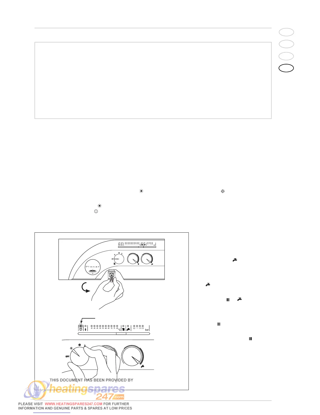
BOILER IGNITION (fig. 1)
Open the gas valve, lower the control panel
cover and activate the boiler by rotating the
selector knob to the summer positio ( ).
The lighting-up of the green led ( ) will
indicate that the apparatus is switched-on
and ready.
–
With the rotary switch in the summer
position ( ) the boiler will start-up
upon demand for domestic hot water,
and run at full power to reach the selec-
ted temperature.
The gas feeding pressure will then auto-
matically vary to ensure that the requi-
red temperature is kept constant.
– With the rotary switch in the winter
position ( ) once the boiler has rea-
ched the value set on the heating poten-
tiometer, it will start to modulate in auto-
matically in order to supply the required
power output to the system. The opera-
tion of the boiler will be stopped through
the intervention of the thermostat or
“Logica Remote Control”.
TEMPERATURES ADJUSTMENT (fig. 2)
– The D.H.W. temperature can be adju-
sted by turning the knob of the D.H.W.
potentiometer ( ). When there is a
demand for hot water, the set tempera-
ture is displayed on the red led scale
from 35÷80°C and the yellow domestic
hot water led lights-up at the same time
( ). When model “BFT” is connected
with a “BT100” tank unit, when there is
no request for heating or D.H.W. produc-
tion (the leds and are off), the tank
unit maintenance temperature will
appear on the red led scale 35÷80°C.
–
The C.H. temperature can be adjusted
by turning the knob of the C.H. potentio-
meter
( ).
The set temperature is indi-
cated on the red led scale from
35÷80°C and the yellow heating led
lights up at the same time
().
If the temperature of the C.H. return
water is lower than around 55° C, con-
densation of the combustion by-products
is obtained, further increasing the effi-
cency of thew thermal exchange.
TURNING THE BOILER OFF (fig. 1)
To turn the boiler off place the selector
WARNINGS
– In case of fault and/or incorrect equipment operation, deactivate it, without making any repairs or taking any direct
action. Contact an authorised technical staff.
– The installation of the boiler and any servicing or maintenance job must be carried out by qualified personnel. Under
no circumstances, the devices sealed by the manufacturer can be tampered with.
– It is absolutely prohibited to block the intake grilles and the aeration opening of the room where the equipment is
installed.
LIGHTING AND OPERATION