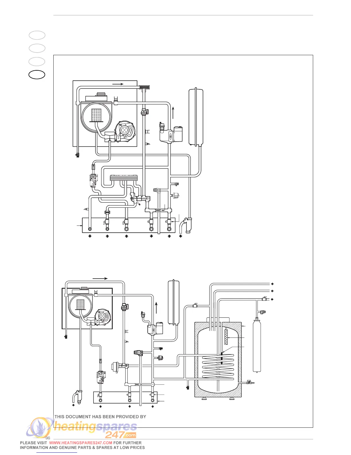
1.4 FUNCTIONAL DIAGRAM
Fig. 2
KEY
1Fan
2 Water-gas exchanger
3 Breather valve
4 Gas valve
5 D.H.W. exchanger
6 Diverter valve with charging
7 C.H. sensor (SM)
8 100°C safety stat
9 Air relief valve
10 Circulation pump
11 Expansion vessel
12 Safety valve
13 Boiler discharge
14 Water pressure transducer
15 Flowmeter
16 Automatic by-pass
17 D.H.W. filter
18 C.H. return cock (optional)
19 C.H. flow cock (optional)
20 D.H.W. cock (optional)
21 Gas cock (optional)
22 Fixing jig
23 D.H.W. sensor
24 90°C limit stat
25 Condensation water trap
26 Gas rate adjuster
27 Motor-operated diverter valve
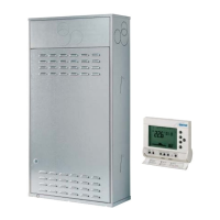
28 “BT100” storage tank (optional)
29 Filling cock (optional)
30 D.H.W. discharge cock
31 Magnesium anode
32 D.H.W. expansion vessel 4 liter (optional)
33 D.H.W. safety valve 7 bar (optional)
34 Aqua Guard Filter System
“BF” model
“BFT” model - “BT100” storage tank