80
IT
ES
PT
GB
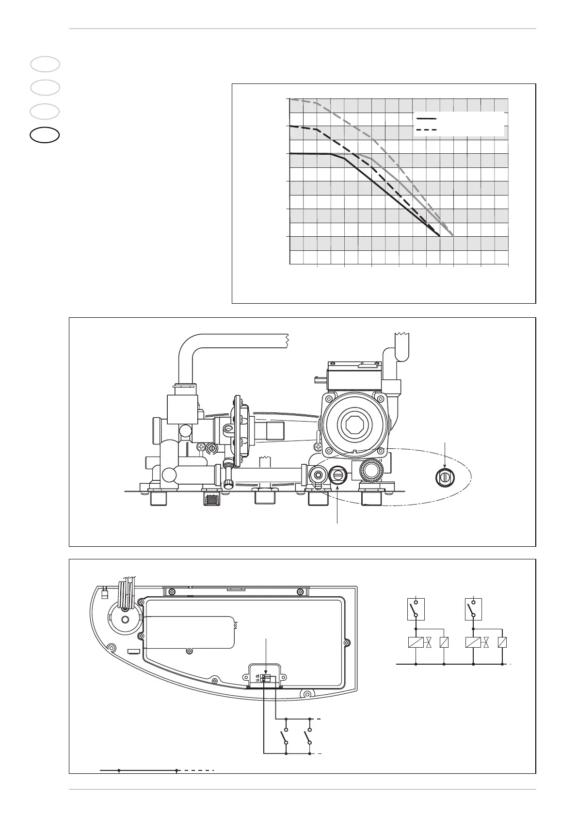
3.8 HEAD AVAILABLE
TO SYSTEM
Residual head for the heating system is
shown as a function of rate of flow in the
graph in fig. 17.
To obtain the maximum head available to
the system, turn off the by-pass by turning
the union to the vertical position (fig. 17/a).
3.9 ELECTRICAL WIRING
OF ZONE HEATING SYSTEMS
When installing a system of this type, use a
separate electrical line to which room ther-
mostats with their local valves will be con-
nected.
Connect micro switches or relay contacts
on terminals 15-16 of the “TA” connector
of the electronic card after removing the
existing jumper (fig. 18).
KEY
TA-TA1 Zone room stat
VZ-VZ1 Zone valve
R-R1 Zone relay
CR-CR1 Relay contact or micro zone valve
NOTE: Relays are used only if the area
valves have no microswitches.
“TA” connector
By-pass on
By-pass off
By-pass on
By-pass off
Fig. 17