8
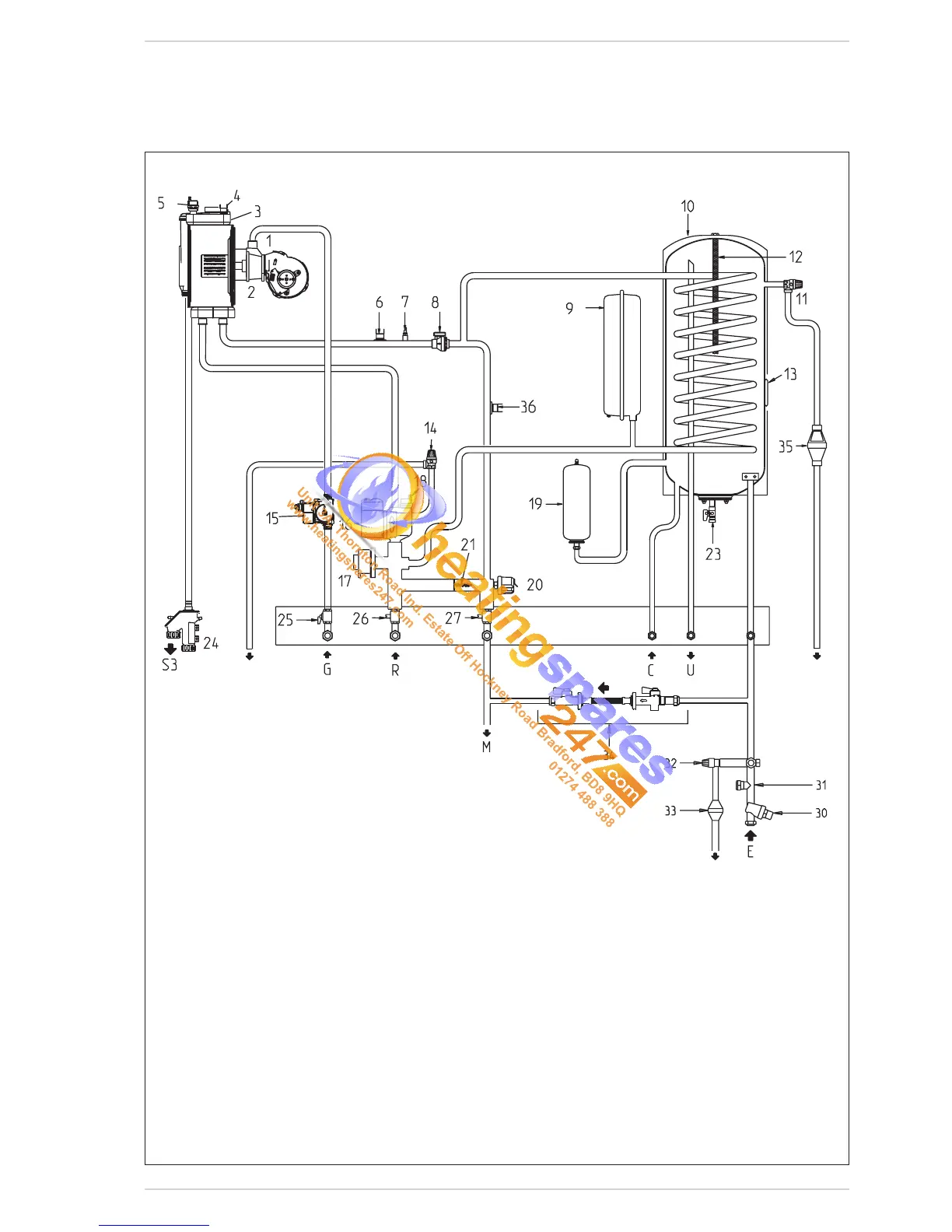
1.5 FUNCTIONAL DIAGRAM
Fig. 2
KEY
1 Fan
2 Air/gas mixer
3 Primary exchanger
4 Limit stat
5 Air relief valve
6 Safety thermostat 100°C
7 C.H. sensor (SM)
8 Flow switch
9 C.H. Expansion vessel
10 D.H.W. tank
11 TPR valve 7 BAR 90°C -TPRV
12 Magnesium anode
13 D.H.W. sensor (SB)
14 C.H. Safety valve 3 BAR
15 Gas valve
16 Pump
17 Diverter valve
18 Air bleed valve
19 D.H.W. expansion vessel
20 Water pressure transducer
21 Automatic bypass
23 D.H.W. drain cock
24 Condensate drain tap
25 Gas cock
26 Heating system return cock
27 Heating system delivery cock
30 Pressure reducing valve 3.5 BAR
31 Single check valve
32 Expansion relief valve 6 BAR
33 Tundish expansion relief valve
34 Filling loop
35 Tundish
36 D.H.W. over heating thermostat 85°C
CONNECTIONS
R C.H. return
M C.H. flow
G Gas connection
E D.H.W. inlet
U D.H.W. outlet
C Recirculation
S3 Condensation outlet
 Loading...