47
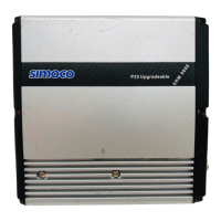
The picture on the left shows the whole rebroadcast setup with the lid off. The radios are
standard SRM9005s but are fitted into a TSF2000, 1U, case and not in their normal
individual aluminium boxes. The necessary heatsink is on the bottom of each radio. The
RJ45 port on the left-hand (TWC) radio is connected to MRMap running on my Eee PC
and the device to the left of the computer, is the diplexer.
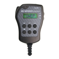
The image above is a close-up of the power/facility connectors. The heavier black lead
between the two D-connectors carries the cross-over connections that duplicate the job
normally handled by the red, RJ45 crossover lead. Both RJ45 connectors are available
for use with either a computer or a control head.