DRAWING REFERENCES
The circuitries for the tone oscillator modules are shown on the following drawings:
2001-6032 WD No. 800-906 (Slow Whoop Oscillator)
2001-6033 WD No. 800-912 (Wail Oscillator)
2001-6034 WD No. 800-907 (Beep Oscillator)
2001-6035 WD No. 800-909 (Horn Oscillator)
2001-6038 WD No. 800-913 (Stutter Oscillator)
2001-6051 WD No. 841-407 (Chime Oscillator)
2001-6052 WD No. 841-400 (Coded Horn Oscillator)
2001-6057 WD No. 556-467 (Hi/Lo Oscillator)
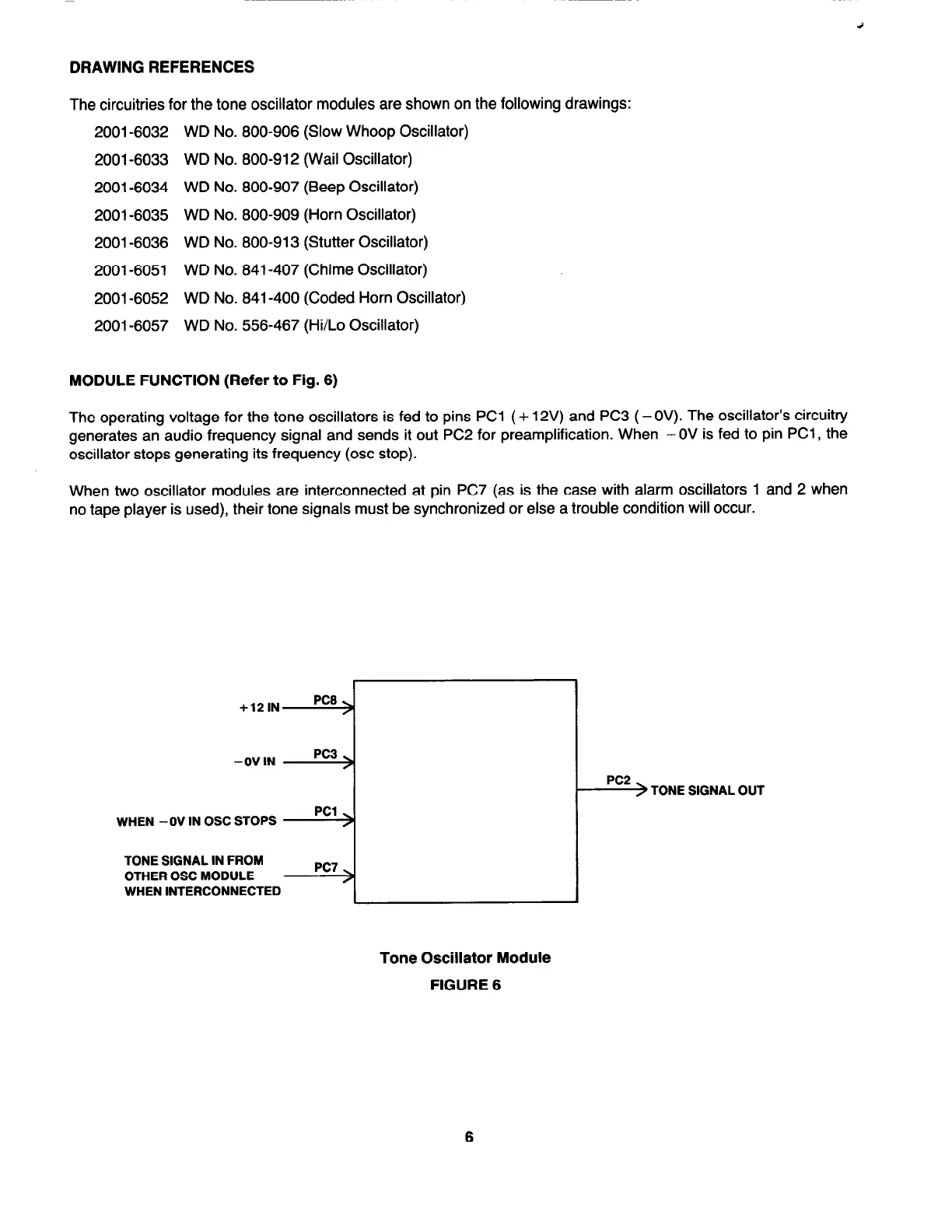
MODULE FUNCTION (Refer to Fig. 6)
The operating voltage for the tone oscillators is fed to pins PC1 (+ 12V) and PC3 (-OV). The oscillator’s circuitry
generates an audio frequency signal and sends it out PC2 for preamplification. When - OV is fed to pin PC1 , the
oscillator stops generating its frequency (osc stop).
When two oscillator modules are interconnected at pin PC7 (as is the case with alarm oscillators 1 and 2 when
no tape player is used), their tone signals must be synchronized or else a trouble condition will occur.
+12lN
PC8
-0V IN
WHEN - OV IN OSC STOPS
TONE SIGNAL IN FROM
OTHER OSC MODULE
WHEN INTERCONNECTED
PC3
PC1
PC7
PC2
) TONE SIGNAL OUT
Tone Oscillator Module
FIGURE 6
6
 Loading...