12
2.3 Power Source Requirements
There are two batteries in the ohmmeter circuits, a NEDA 13F D size cell that
furnishes 1.5 volts for the R X 1 and R X 100 ranges and a NEDA 1604 battery that
furnishes 9 volts for the R X 10,000 range. The 1.5 volt D cell is held in place with
two spring clips which also serve as battery contacts. The 9-volt battery is held in
place with a spring clip but contact is made with a separate connector that is
polarized. (Always observe correct polarity when replacing the 1.5-volt D cell.)
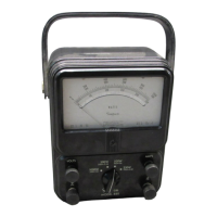
2.4 Operating Position
A handle is attached to the side of the Instrument case. The handle may be used
to support the Instrument in a convenient, sloping position for easy viewing. The
VOM case can also be placed either in a vertical or horizontal position. The
horizontal position promises greater accuracy since the Instrument is calibrated
in this position.
3. CONTROLS, JACKS AND INDICATORS
The functions of all the controls, jacks and indicators used to operate the Simpson
260-8 are described in this section. Become familiar with each item before oper-
ating the Instrument.
3.1 Front Panel Description
Figure 3-1 depicts the front panel controls, jacks and indicators described below.
1. Front Panel: The 260-8 Volt-Ohm-Milliammeter is a large, easy-
to-read 4-1/4” indicating Instrument. Below the In-
strument are four controls and eight circuit jacks.
2. Range Switch: This switch may be rotated in either direction to
select any one of the available voltage, current, or
resistance ranges.
3. Function Switch: The function switch has four positions: Off, +DC, –
DC, and AC Volts Only. To measure DC current or
voltage, set the function switch at the –DC or +DC
position, depending on the polarity of the input sig-
nal. To measure AC voltage set the function switch
to the AC position. For resistance measurement,
the switch may be set in either the +DC or –DC
position. The polarity of the test voltage will be as
marked at the jacks when the switch is in the +DC
position and reversed in the –DC position. Set this
switch to off when not using the meter to take mea-
surements.
4. Zero Ohms: This control is used when measuring resistance to
calibrate the ohms range selected to read zero with
the test leads shorted. Refer to paragraph 4.20.

 Loading...