13
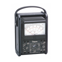
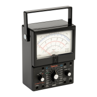
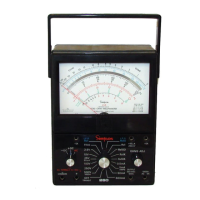
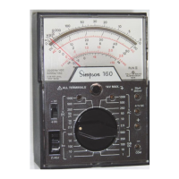
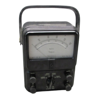
5. Circuit Jacks: There are eight jacks on the front panel marked
with the functions they represent. These jacks pro-
vide the electrical connections to the test leads. The
COMMON (–) jack is used as the reference point
for the measurement of all the functions with the
exception of the 10A range. (Refer to the Opera-
tion Section 4 for details.)
6. Pointer Adjust For Zero: This control is used to mechanically zero the Instru-
ment. With the function switch set to an operating
position (+DC, –DC, or AC volts only), and no ap-
plied input, the pointer should read zero. If it does
not, use a screwdriver to turn this adjustment until it
does. Once this adjustment is made, back off slightly
so that the pointer rests freely over the zero mark.
Figure 3-1. Front Panel Controls, Jacks and Indicators
D
.C.
D
.C
.
500 MA.
2.5 V.
10 V.
1V.
25 V.
50 A.
AMPS.
250 V.
500 V.
I000 V.
100MA.
10MA.
AMPS.
1MA.
R x 1
R x I0,000
ZERO OHMS
-10 A.
OUTPUT
350 VDC
MAX.
+
COMMON
-
A.C. VOLTS
ONLY
- D.C.
+ D.C.
OFF
A.C.
A
.C
.
O
H
M
S
OHMS
2.5 V.A.C.
DB
260
ALL TERMINALS 1 V MAX
1
6
4
2
5
3
R X I00
500 V.
A.C. D.C.
1000 V.
A.C. D.C.
+1V.
+10A
50 AMPS.
250 MV.
+

 Loading...