18
4.9 DC Voltage Measurement 0-1000V Range
Use extreme care when working with high voltage circuits. Do not touch the
Instrument or test leads while power is on in the circuit being measured.
Before proceeding with the following steps, review the Safety Precautions in
paragraph 4.1.
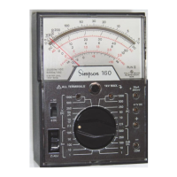
a. Set the function switch at +DC (Fig-
ure 4-3).
b. Set the range switch at the 250V/
500V/1000V position.
c. Plug the black test lead into the –
COMMON jack and the red test
lead into the 1000V jack.
d. Be sure power is off in the circuit
being measured and all capacitors
discharged. Connect the black test
lead to the negative side of the cir-
cuit being measured and the red
test lead to the positive side of the
circuit.
e. Turn on power in circuit being mea-
sured.
f. Read the voltage using the 0-10 fig-
ures on the black scale marked DC.
Multiply the reading by 100.
NOTE: Turn off power to the circuit and
wait until the meter indicates zero
before disconnecting the test leads.
4.10 AC Voltage Measurement 0-2.5 ~ 0-250V Range
Branch and distribution circuits (120/240/480V etc.) can deliver dangerous ex-
plosive power momentarily into a short circuit before the fuse/breaker opens the
circuit. Make certain that the Instrument switches are set properly, jacks are
connected properly, and that the circuit power is turned off before making con-
nections to such circuits.
The 260 responds to the average value of an AC waveform. It is calibrated in
terms of the RMS value of a pure sine wave. If the waveform is nonsinusoidal, and
depending upon its waveform, the reading may be either higher or lower than the
true RMS value of the measured voltage. Thus an error may be introduced if the
260 is used to measure a nonsinusoidal waveform. Also, accuracy is lessened at
higher input frequencies (Figure 4-4).
!
Figure 4-3. Jacks and Switch
Positions for Measuring DC
Voltage, 0-1000V Range
D
.C
.
D
.C
.
250 V.
500 V.
I000 V.
COMMON
-
- D.C.
+ D.C.
260
ALL TERMINALS 1 V MAX
1000 V.
A.C. D.C.
!

 Loading...