21
jack. Do not touch the Instrument or test leads while the power is on in the circuit
being measured.
Before proceeding with the fol-
lowing steps, review the Safety
Precautions in Paragraph 4.1.
a. Set the function switch at
AC (Figure 4-7).
b. Set the range switch at
250V/500V/1000V position.
c. Plug the black test lead into
the -COMMON jack and the
red test lead in the 1000V
jack.
d. Be sure the power is off in
the circuit being measured
and that all its capacitors
have been discharged.
e. Connect the test leads
across the circuit voltage to
be measured with the black
lead to the grounded side.
f. Turn on the power in the cir-
cuit being measured.
g. Read the voltage on the red
scale marked AC. Use the
0-10 figures and multiply by 100.
4.13 Output Voltage Measurement
It’s often necessary to measure the AC component of an Output Voltage where
both AC and DC voltage levels exist. This occurs primarily in amplifier circuits.
The 260-8 has a 0.1 mfd, 400
volt capacitor in series with the
OUTPUT jack. The capacitor
blocks the DC component of the
current in the test circuit, but al-
lows the AC or desired compo-
nent to pass on to the indicating
instrument circuit. The blocking
capacitor may alter the AC re-
sponse at low frequencies but
is usually ignored at audio fre-
quencies (Figure 4-8).
Do not connect the OUTPUT
jack to a circuit in which the DC
voltage component exceeds
350V.
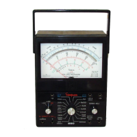
FIGURE 4-7. Jacks and Switch Positions
for Measuring AC Voltage 0 Through
1000V Range
2.5 V.
10 V.
1V.
25 V.
50 A.
AMPS.
250 V.
500 V.
I000 V.
ZERO OHMS
COMMON
-
A.C. VOLTS
ONLY
A
.C
.
A
.C
.
260
ALL TERMINALS 1 V MAX
500 V.
A.C. D.C.
10
+10
+8
+6
+4
+2
0
-2
-4
-6
-8
-10
10Hz 100Hz 1KHz 10KHz 100KHz 1MHz
FREQUENCY
2.5 VAC RANGE
10VAC RANGE
25/50 VAC RANGE
250 VAC RANGE
OUTPUT RANGES
Figure 4-8. Frequency
Response Output Ranges

 Loading...