26
d. Observe the reading on the
OHMS scale at the top of the
dial.
NOTE: The OHMS scale reads
from right to left for increasing
values of resistance.
e. To determine the actual re-
sistance value, multiply the
reading by the factor at the
switch position. (K on the
OHMS scale equals one
thousand.)
4.16.2 Resistance Measurement of Semiconductors
Make sure that the OHMS range being used will not damage any of the semicon-
ductors (refer to Table 1-1, item 8, Section I).
If there is a “forward” and “backward” resistance such as in diodes, the resistance
should be relatively low in one direction (for forward polarity) and higher in the
opposite direction.
Rotate the function switch between the two DC positions to reverse polarity. This
will determine if there is a difference between the resistance in the two directions.
To check a semiconductor in or out of a circuit (forward and reverse bias resis-
tance measurements) consider the following before making the measurement:
a. The polarity of the battery voltage will be as marked at the jacks when the
switch is in the +DC position and reversed in the –DC position.
b. Ensure that the range selected will not damage the semiconductor. (Refer to
Table 1-1, item 8, and review the specification limits of the semiconductor
according to the manufacturer’s ratings.)
c. If the semiconductor is a silicon diode or conventional silicon transistor, no
precautions are normally required.
d. If the semiconductor material is germanium, check the ratings of the device
and refer to Table 1-1, item 8.
NOTE: The resistance of diodes will measure differently from one resistance
range to another on the VOM with the function switch in a given position. For
example, a diode which measures 80 ohms on the R X 1 range may measure 300
ohms on the R X 100 range. The difference in values is a result of the diode
characteristics and is not indicative of any fault in the VOM.
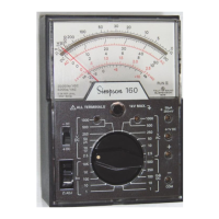
R x 1
R x I0,000
+
COMMON
-
- D.C.
+ D.C.
O
H
M
S
OHMS
260
ALL TERMINALS 1 V MAX
R X I00
Figure 4-12. Jacks and Switch
Positions for Measuring
Resistance

 Loading...