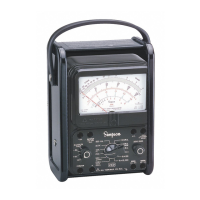
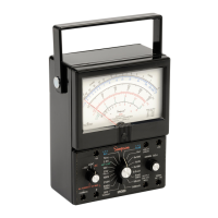
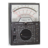
27
5. OPERATOR MAINTENANCE
The following paragraphs in this section describe battery replacement, fuse re-
placement, and preventive maintenance procedures for the 260-8.
5.1 Inspection
The user is protected from electrical shock by the insulation of the 260 and its test
leads. Frequently examine them for any insulation damage such as cracks, cuts,
chips, burns or deterioration that expose internal metal parts or reduce the spac-
ing between such metal parts and hand contact by the operator.
Make certain that the battery compartment cover is securely fastened in place
before the Instrument is used.
Do not use an Instrument with a broken meter glass.
If the battery compartment cover is removed for any reason, check that the proper
fuses are being used.
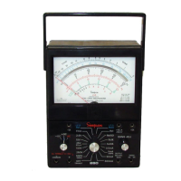
5.2 Battery Replacement
a. Two batteries supply power for resistance measurements, a 1.5-volt D cell
and a 9-volt battery. When it is no longer possible to adjust the pointer to zero
for the R X 1 and R X 100 ranges (refer to ZERO OHMS ADJUSTMENT
paragraph 4.16), replace the 1.5-volt cell. When it is no longer possible to
adjust the pointer to zero on the R X 10,000 range, replace the 9-volt battery.
b. To install or replace a battery, de-energize and disconnect test leads from the
Instrument, then remove the cover to the externally accessible battery com-
partment by loosening the single captivated screw.
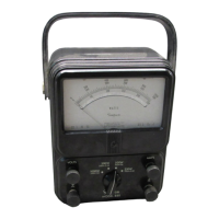
Figure 5-1. Battery and Fuse Compartment

 Loading...