SINAMICS G120
Standard inverters 0.37 kW to 250 kW (0.5 hp to 400 hp)
CU230 Control Units
4/16
Siemens D 11.1 · 2009
4
■
Integration
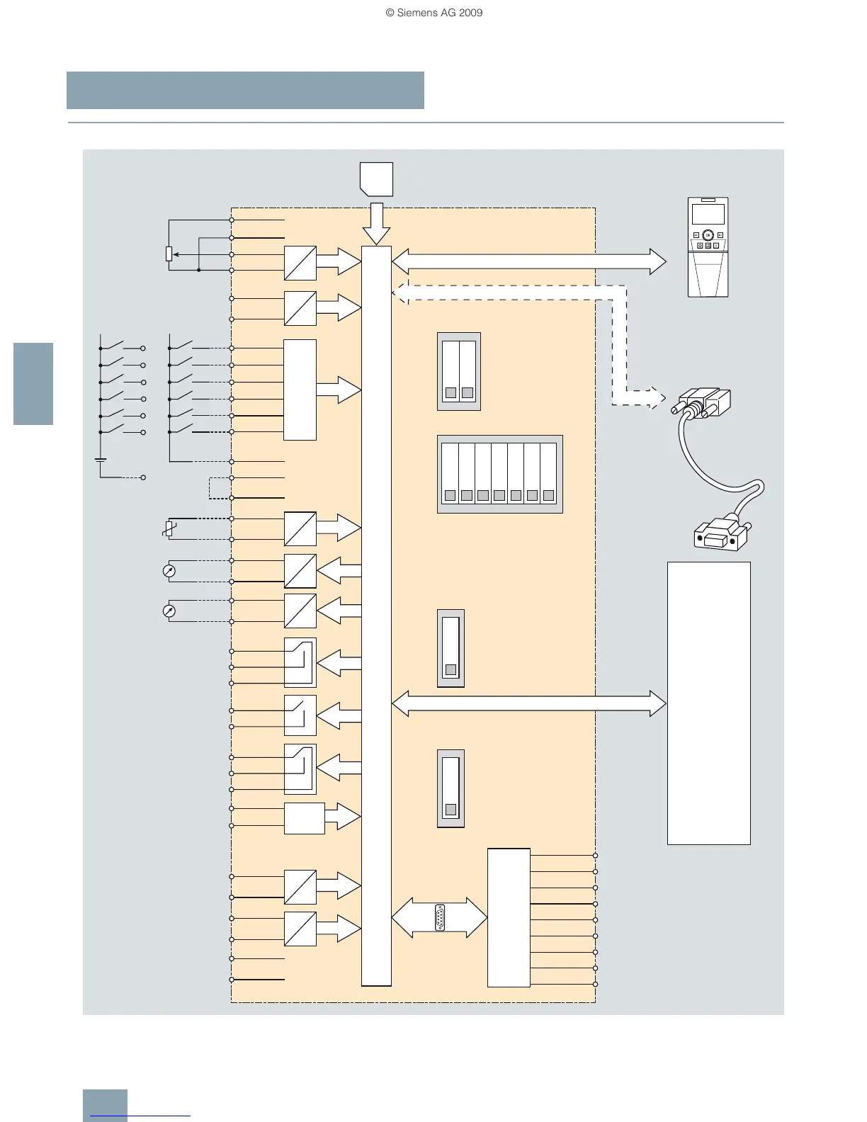
CU230P-2 CAN Control Unit connection diagram
G_D011_EN_00212
IOP/IOP handheld
Voltage output 10 V
Temperature sensor
NI1000 or AI2+
Temperature sensor
NI1000 or AI3+
PM-IF interface
0 to 10 V
0 to 20 mA
PC to inverter
connection kit
OFF
ON
OFF
ON
OFF
ON
0 to 20 mA
max. 500 Ohm
0 to 20 mA
max. 500 Ohm
≥ 4.7 kOhm
IOP/IOP handheld interface
USB interface for PC tools
Digital inputs
* = Not connected
From
external
source
DIP switch
Analog inputs
CURRENT
DIP switch
Temperature sensor NI1000
CANopen address DIP switch
CANopen interface
SUB-D-type connector
DIP switch
Bus termination
(optional shield)
(optional CAN ground)
(1)
Bit 1
(64)(16) (32)(2) (4) (8)
Bit 0
Bit 3
Bit 2
Bit 5
Bit 6
Bit 4
69
17
16
8
7
6
5
-
+
24 V
DI5
DI4
DI3
DI2
DI1
DI0
MMC
PTC/KTY
Power Module
AI1
AI0
DO0
DO2
DO1
AO1-27
AO1+26
D
A
D
A
9
*8
7
6
5
4
CAN_GND
*
(CAN_SHLD)
(GND)
CAN_L
ISO
CAN_H
3
2
1
0 V32
+24 V31
U0V28
NO21
COM22
NO24
NC23
COM25
NO19
NC18
COM20
AO0-13
AO0+12
15
14
69
U24V9
DI517
DI416
DI38
DI27
DI16
DI05
AI1-11
AI1+10
AI0-4
AI0+3
2
1
0 V
+ 10 V
D
A
A
D
A
D
GND
36
+ 10 V OUT
35
53
52
51
50
D
A
D
A
GND
GND
AI2+/
NI1000
AI3+/
NI1000
DI COM
Control Unit
CU230P-2 CAN
NI1000
*
 Loading...