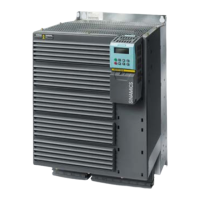
SINAMICS G120
Standard inverters 0.37 kW to 250 kW (0.5 hp to 400 hp)
CU240 Control Units
4/20
Siemens D 11.1 · 2009
4
■
Design
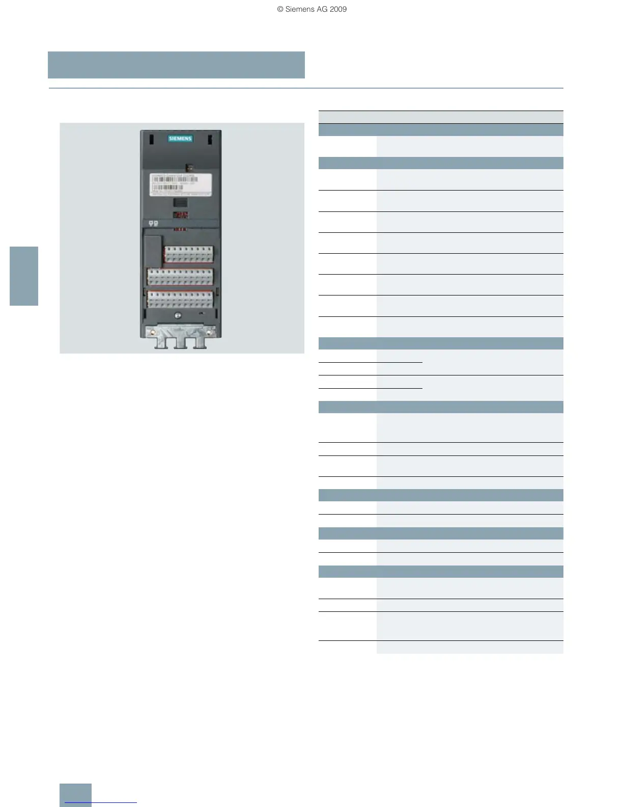
CU240E Control Unit
CU240E Control Unit without terminal cover
Terminal No. Signal Features
Digital inputs (DI)
5…8,
16.17
DI0 … DI5 Freely programmable (isolated)
5.5 mA/24 V
Digital outputs (DO)
18 DO0, NC Relay output 1
NC contact (0.5 A, 30 V DC)
19 DO0, NO Relay output 1
NO contact (0.5 A, 30 V DC)
20 DO0, COM Relay output 1
Common contact (0.5 A, 30 V DC)
21 DO1, NO Relay output 2
NO contact (0.5 A, 30 V DC)
22 DO1, COM Relay output 2
Common contact (0.5 A, 30 V DC)
23 DO2, NC Relay output 3
NC contact (0.5 A, 30 V DC)
24 DO2, NO Relay output 3
NO contact (0.5 A, 30 V DC)
25 DO2, COM Relay output 3
Common contact (0.5 A, 30 V DC)
Analog inputs (AI)
3 AI0+ 0…10V, –10…+10V, 0/2…10V or
0/4 … 20 mA
4 AI0-
10 AI1+ 0…10V, 0…20mA
11 AI1-
Analog outputs (AO)
12 AO0+ Freely programmable
(0/4 … 20 mA with max. 500 Ω,
0/2 … 10 V with min. 500 Ω)
13 AO0- M
26 AO1+ Freely programmable
(0/4 … 20 mA with max. 500 Ω)
27 AO1- M
PTC/KTY interface
14 PTC+ Positive PTC/KTY input
15 PTC- Negative PTC/KTY input
Serial RS485 interface
29 P+ RS485 A, USS protocol
30 N- RS485 B, USS protocol
Power supply
9 U24V Isolated user power supply
+24 V at 100 mA
28 U0V Isolated user reference voltage
1 +10 V Non-isolated, regulated
10 V power supply for I/O –
max. 10 mA
2 0V Power supply reference
 Loading...