SINAMICS G120
Standard inverters 0.37 kW to 250 kW (0.5 hp to 400 hp)
SINAMICS G120 standard inverters
4/4
Siemens D 11.1 · 2009
4
■
Benefits
7 Modularity ensures flexibility for a drive concept that is fit-for-
the-future
- Modules can be replaced under voltage (hot swapping)
- Pluggable terminals
- The modules can be easily replaced, which makes the
system extremely service friendly.
7 The safety functions make it easier to integrate drives into
safety-oriented machines or plants
7 Communications-capable via PROFINET or PROFIBUS with
PROFIdrive Profile 4.0
- Reduced number of interfaces
- Plantwide engineering
- Easy to handle
7 The innovative circuit design (bidirectional input rectifier with
“pared-down” DC link) allows the kinetic energy of a load to be
fed back into the supply system when Power Modules PM250
and PM260 are used. This feedback capability provides enor-
mous potential for savings because generated energy no
longer has to be converted into heat in a braking resistor
7 Innovative SiC semiconductor technology ensures that when
a PM260 Power Module is used, the inverter is more compact
than a comparable standard converter with an optional sine-
wave filter for the same power rating
7 An innovative cooling concept and coated electronic modules
increase robustness and service life
- External heatsink
- Electronic components are not located in air duct
- Control Unit that is completely cooled by convection
- Additional coating of the most important components
7 Simple unit replacement and quick copying of parameters
using the optional Basic Operator Panel or the optional MMC
memory card
7 Quiet motor operation as a result of the high pulse frequency
7 Compact, space-saving design
7 Software parameters for simple adaptation to 50 Hz or 60 Hz
motors (IEC or NEMA motors)
7 2-/3-wire control (static/pulsed signals) for universal control
via digital inputs (only CU240 Control Units)
7 Engineering and commissioning with uniform engineering
tools such as SIZER, STARTER, and Drive ES: ensure fast en-
gineering and easy commissioning – STARTER is integrated in
STEP 7 with Drive ES Basic with all the advantages of central
data storage and totally integrated communication
7 Certified worldwide for compliance with CE, UL, cUL, c-tick
and Safety Integrated according to IEC 61508 SIL 2
■
Applications
SINAMICS G120 is ideally suited
• as a universal drive in all industrial and commercial applica-
tions
• e.g. in the automotive, textile, printing and chemical industries
• for higher-level applications, e.g. in conveyor systems
■
Design
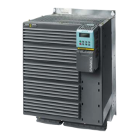
SINAMICS G120 standard inverters are modular frequency in-
verters for standard drives. Each SINAMICS G120 comprises
two operative units – the Power Module and Control Unit. Each
Control Unit can be combined with each Power Module.
Guidelines for module selection
The procedure to select a complete SINAMICS G120 frequency
inverter should be as follows:
Control Units
The Control Unit performs closed-loop control functions for the
inverter. In addition to the closed-loop control, it has additional
functions that can be adapted to the particular application
through parameterization.
Two series of Control Units are available for SINAMICS G120
corresponding to their software packages (CU230 and CU240).
Each Control Unit comprises a defined I/O quantity structure, a
special fieldbus interface and possible additional safety func-
tions. The following Control Units and accessories are available
for standard SINAMICS G120 inverters:
CU230 Control Units
The CU230P-2 Control Units have been specifically designed for
pump, fan and compressor applications. The following three ver-
sions are available:
• CU230P-2 HVAC
• CU230P-2 DP
• CU230P-2 CAN
CU240 Control Units
Several Control Units are available in different versions:
• CU240E
• CU240S
• CU240S DP
• CU240S DP-F
• CU240S PN
• CU240S PN-F
1. Select a suitable Control Unit (depending on the required commu-
nication, hardware and software version and safety functionality)
2. Select a suitable Power Module (depending on the power and
technology required)
3. Select the optional and additional components. There are a large
number of components for expanding the system (e.g. line-side
power components, DC link components, load-side power compo-
nents, and supplementary system components). However, it
should be noted that not all of the components are required for all
of the Power Modules (example: Braking resistors are not required
for the PM250 and PM260 Power Modules!). The precise data is
provided in the technical specifications tables of the particular
components.
 Loading...