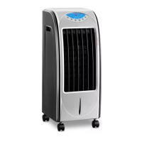
CON.AC-700I
CON.AC-700
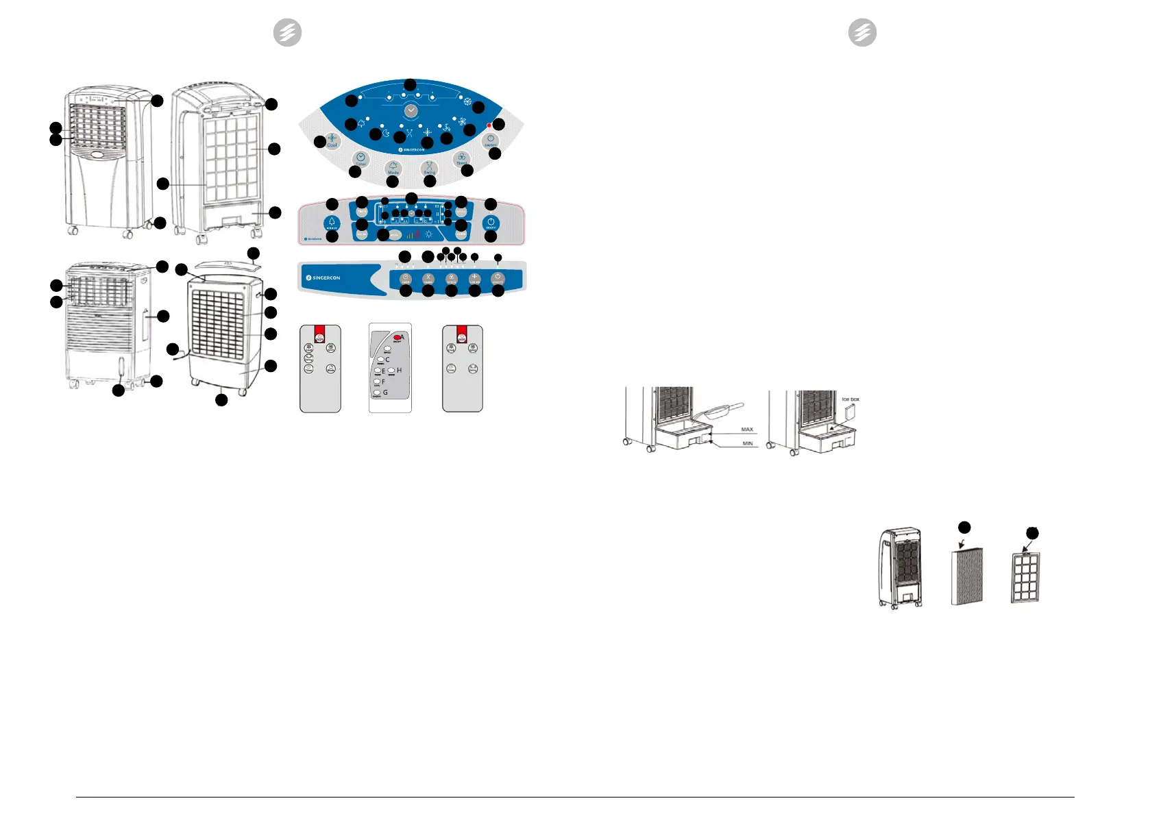
1. Control panel
2. On / O button of the heating function
3. Wheels
4. Water level indicator
5. Horizontal jalousies
6. Vertical jalousies
7. Inlet of water and ice
8. Power cord
9. Internal lter with Honey comb structure
10. Water tank
11. External lter
12. Handle
13. Water outlet
14. Ice tank
15. Top cover
4.2 Preparing for use
It is necessary to install the attached wheels in the device.
Place the device in a vertical position on a at and stable
surface. The device is equipped with lters. Before using the
device it is necessary to always make sure whether the lters
are installed in the device. The lack of the external lter
may cause damage to the device by getting contaminants
into its inside. The internal lter enables functioning of the
cooling process and additionally it also lters the air and
moisturizes it (during the cooling process).
4.3 Device use
Description of control panels and wireless remote controls
6
5
1
3
11
8
9
10
6
5
1
7
3
4
14
8
13
10
11
9
12
15
CON.AC-500H / CON.AC-500
CON.AC-700
E1
D1
D2
D3
C1
F1
B1
B2
B3
F
E
D
C
B
A
A
F
C
E
B
D
A1
CON.AC-500H/
CON.AC-500
CON.AC-700I
CON.AC-700
CON.AC-700I
G1
G
E
F
H
C
B
A1
A
E1
C1
F1
H1 H2 D1 D3
B3
B2
B1
E1 C1
B2
E C
B/D
F A
D2
D3B3 F1B1
A1
A
F
C
E D
G
B
H
A
F B/D
E C
A. On / o switch
A1. – information on switching the device on / o
B. Ventilation speed adjustment button
B1. – low ventilation force
B2. – average ventilation force
B3. – strong ventilation force
C. Button for switching on the automatic movement of
the jalousie
C1. –information on activation of the jalousie
movement function
D. Ventilation mode selection button
D1. – normal mode
D2. – natural mode
D3. – night mode
E. Timer
E1. – time of automatic device shutdown
F. Button for switching on the cooling function
F1. – information on activation of the cooling
function
G. Button for switching on the air ionization function
G1. – information on activation of the ionization
function
H. Button for switching on the heating function
H1. – low heating power
H2. – high heating power
The elements marked with the numbering A1 – H2 are
diodes informing about the activation of a given device
function. If the function is active, the diode lights up,
otherwise it is o.
Heating function
• The CON.AC-500H AND CON.AC-700I models have
the air heating function.
EN
10
• In the CON.AC-500H model, the function is activated
manually using the button (2), however, it will work
only when the device is switched on (the On / O
button (1) is on – the diode A1 lights up). There is
only one stage of heating setpoint.
Note: Always set the switch (2) to the O position,
if we turn o the whole device (despite turning
o the device with the remote control, the user
must approach it and turn o the heating function
manually).
• The CON.AC-700I model has an automatic activation
of the heating function from the level of the control
panel or the wireless remote control. The heating
function has the option of the two-stage selection of
the heating power (change of the stage by pressing
the button (H)). You can disable the option by pressing
the (H) button on the panel or on the wireless remote
control.
Cooling function
• All models of the devices have the air cooling function.
• In order to activate the function, the tank of the device
must be lled with water and previously frozen cooling
cartridges or ice cubes. It is forbidden to activate the
function without the tank lled with water.
• Topping up the water tank:
In the CON.AC-700I, CON.AC-500H and CON.AC-500
models, it is necessary to pull out the water tank and
ll it with water and frozen cooling cartridges or ice
cubes – this is shown in the picture below:
• In the CON.AC-700 model, the water tank is topped
up by pouring clean water and dropping ice cubes
through the inlet hole (7). Note: It is forbidden to use
cooling cartridges in this model! Observe the level of
water being poured on the water level indicator (4).
• Regularly observe the water level in the tank in the
course of the device operation. If necessary, ll up the
water shortages.
Setting the operation time
The operating time of the device is set by single pressing the
button (E). Each pressing causes to add 1h starting from 1 to
12h (in the case of the CON.AC-700 model, addition of 0.5h
starting from 0.5 to 7.5h).
Operation
• Connect the device to the power supply source.
• Switch on the device with the On / O button (A).
• Set the device operation manner according to own
preferences. The number of available options from
among the operating modes depends on the device
model.
• Single pressings of the option data buttons cause their
activation, the next pressings in case of the buttons
with the single selection causes deactivation of the
given option. In the case of buttons with possibilities
of selection of the functioning option, single pressings
will cause jumping between subsequent options, after
Clean the lters with water with addition of a mild detergent.
If required the external lter can be soaked in water for
approx. 10 minutes and then it is necessary to remove
the dirt with a soft brush. Before retting the lter, dry it
completely! Place the cleaned lters back in the device,
screw on.
• Cleaning the water tank:
In case of models CON.AC-700I, CON.AC-500H and CON.
AC-500, it is necessary to drain water from the tank, then
pull it out and clean it with a mild agent.
In the case of the CON.AC-700 model, in order to clean the
tank, it is necessary to disassemble the lters at rst and
thus get access to the tank. Drain the dirty water through
the water outlet.
9
11
reviewing all options, the next pressing will cause
deactivation of the option.
Depending on the device model, the following options are
available:
1. COOL/ COOL AIR– cooling option
2. TIMER – minute timer
3. MODE – selection of the ventilation mode
4. SWING – switching on / o the jalousie movement
5. SPEED – ventilation speed regulation
6. WARM – heating option
7. IONIZER – switching on / o the ionization function
• The user has the possibility to manually set the
ventilation angle (manually setting horizontal
jalousies).
• In case of operating the device with a remote control,
it is necessary to direct the remote control transmitter
towards the device.
• Always turn o the device after the end of its use. It is
best to disconnect the device from the power supply
source.
• In case of moving the device to another location, it
is necessary to use the handles if they are installed
in the device and the wheels. The water tank must
be emptied for the period of transport. Transport the
device only and exclusively in the vertical position.
4.4 Cleaning and maintenance
• Before cleaning, maintenance and when not in use,
make sure the power cable is disconnected and the
device has cooled down.
• Use cleaners without corrosive substances to clean
each surface.
• Clean the device with a soft cloth. It is forbidden to
pour water on the device.
• Regularly clean the lters installed in the device.
Cleaning the external and internal lter:
Dismantle the external lter by unscrewing it from the back
part of the device housing. Dismantling the external lter
(11) will enable access to the internal lter with a honey
comb structure (9).
EN
11
B/D
07.09.2018
 Loading...