light)
7. Power supply for fittings: +12VDC(Electric current ≤100mA);
8. Photocell input (N.C.); short out the device with terminal 9(GND) if not used.
9. GND
10. Loop detector (sensor coil) connector (N.O.)
In the closing process, once vehicles are detected by the loop detector, the gate will open
immediately; when the vehicle passes, the gate will close automatically. When the gate is in
a halted state, it will keep this state when vehicles are detected; after the vehicle passes, the
gate will close automatically.
In the above loop detector function, users can make the gate close automatically 12
seconds later after the vehicle passes. Change the No.4 key of the dip switch on circuit
board, and the gate will close automatically 12 seconds later after the vehicle passes.
11. Close limit switch
12. Limit switch and other input signal common terminal
13. Open limit switch
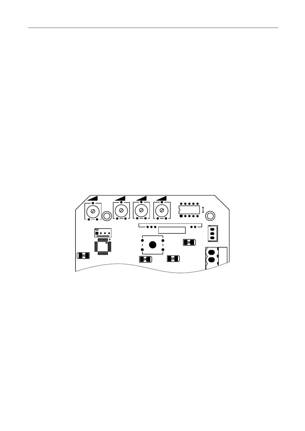
Function adjustment
Functional parameters of the control board equipped with microprocessor can be adjusted through
potentiometer and dip switch, so as to meet different installation requirements.
1313
1212
SPEEDSPEED GNDGND VCCVCC
OFFOFF
ONON
X1X1
HALLHALL
U2U2
S1S1
VR3VR3
VR4VR4
LEARNLEARN
POWERPOWER
J1J1
1313
VR1VR1 VR2VR2
SW1SW1
1 2 3 4 5
Figure 16
Adjusting knob
VR1: When meet obstacle reverse function is enabled (DIP switch 5 on OFF position and the motor
assembled with the hall line). This knob is used for sensitivity adjustment of meeting obstacle.
Clockwise rotation to reduce sensitivity of obstacle, counter-clockwise rotation to increase sensitivity
of obstacle.
When meet obstacle reverse function is disabled (DIP switch 5 on ON position), this knob is used for
motor working total time adjustment. Clockwise rotation to increase, counter-clockwise rotation to
reduce. The total time can be set to 10 seconds as minimum and 90 seconds as maximum.
VR2: For brake force adjustment in limit position.
Clockwise rotation to increase, counter-clockwise rotation to reduce.
Rotate to the minimum to cancel brake function in place.
VR3: For slow stop width adjustment.
Clockwise rotation to increase, counter-clockwise rotation to reduce.
 Loading...