Do you have a question about the SKF Lincoln 85307 and is the answer not in the manual?
Key functionalities and capabilities of the controller.
Technical details like voltage, current, dimensions, and temperature range.
Specific operational guidelines to ensure safe usage.
Explains the meaning of warning, caution, and danger signals.
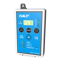
Detailed explanation of each numbered item in the keypad diagram.
Explains LED codes for single-line, progressive-line, and dual-line systems.
Explains LED codes for normally open (n-0) and normally closed (n-C) sensors.
Explains codes for external lamp status and non-fatal errors.
Explains codes for run time and pause time indicators.
Explains codes for fault time and vent time.
Explains codes for confirming program changes and test mode.
Explains codes for sensor time out and fatal errors.
Explains codes for run time and standby mode.
Steps for selecting dual-line system type using pressure switches.
Procedure for setting the pause time duration using the controller.
Configuration of pressure switch time out and sensor type (normally open/closed).
Steps to confirm setup choices and set the number of run cycles.
Setting up low level detection and confirming sensor type.
Configuring error indicators and external warning lamp status.
Procedure for entering and confirming test mode before exiting setup.
Controller operation during the pump run cycle, showing countdown.
Controller operation during the pump pause cycle, showing countdown.
Operation during vent cycles in dual-line systems.
Cycle begins pumping through line B, pressurizing until pressure switch closes.
Flow changes; line A pressurizes, line B vents; pump stops until B vents.
Pump pressurizes line A until change-over valve setting is reached.
Line B pressurizes; pump stops and pauses until line A pressure switch opens.
Line A pressure switch opens, pump restarts, cycle completes, and pump resumes pause.
Diagram showing connections for motor, switches, and power supply.
Diagram showing connections for motor, vent valve solenoid, and power supply.
Explanation of fault codes and how to reset the unit after a fault.
Setting up microswitch monitoring and system type for half cycles.
Configuring sensor type (normally open/closed) and error indicators (fatal/nonfatal).
Setting external lamp status and entering test mode for confirmation.
Operation during pump run in half-cycle mode.
Operation during pump pause in half-cycle mode.
Pump runs, time counts up until change-over valve activates microswitch.
Pump stops, controller resumes pause time, other LEDs illuminate.
Pump pressurizes line A; LED flashes while pump works.
Change-over valve activates microswitch, pump stops, system resumes pause.
Diagram showing connections for motor, microswitch, and power supply.
Explanation of fault codes and how to reset the unit after a fault.
Information on where to find general conditions of sales for warranty details.
| Type | Control Unit |
|---|---|
| Model | 85307 |
| Brand | SKF Lincoln |
| Voltage | 24 V DC |
| Protection class | IP65 |
| Application | lubrication systems |