Do you have a question about the SKF TKSA 20 and is the answer not in the manual?
Explains how the TKSA 20 system uses two measuring units with laser diodes and detectors to calculate misalignment.
Defines the terms 'Movable machine' and 'Stationary machine' for the alignment procedure.
Uses clock analogy (12, 3, 9 o'clock) to define measuring unit positions for alignment.
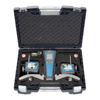
Lists all items included in the TKSA 20 kit, including display unit, measuring units, and accessories.
Details the LCD display and the function of each button on the TKSA 20 display unit.
Illustrates and labels the mechanical fixture, including laser emission, detector, and adjustment mechanisms.
Provides detailed specifications for measuring units, display unit, and the complete system.
Explains how to switch between metric and imperial measurement units.
Advises checking for 'soft foot' condition before alignment, detailed in chapter 3.10.
Details how to attach the S-marked and M-marked measuring units to the shafts using fixtures and chains.
Instructions for switching on the display unit and aiming the laser lines to the 12 o'clock position.
Explains how to hit the target with laser lines and use adjustment mechanisms for coarse and fine positioning.
Details how to perform rough alignment when laser lines might fall outside detector areas, using 9 and 3 o'clock positions.
Explains how to measure and input the three key machine dimensions (A, B, C) into the tool.
Guides through rotating the shafts and measuring at 9 and 3 o'clock positions, using the display's guidance.
Explains how to read coupling values (angle, offset) and feet values (F1, F2) from the display.
Details how to adjust the measuring units to the 12 o'clock position for vertical alignment.
Provides acceptable misalignment tolerances and explains how to adjust feet for vertical alignment based on displayed values.
Details how to move units to the 3 o'clock position and adjust feet for horizontal alignment based on tolerances.
Explains how to interpret horizontal alignment results and how to verify the alignment by repeating the measurement sequence.
Details the steps to detect and correct 'soft foot' conditions using the tool's soft foot mode.
Lists the various data fields that can be included in a shaft alignment report.
Describes how to perform alignment when limited space restricts the measuring unit rotation to 9 or 3 o'clock.
Provides solutions for common issues like the system not switching on, no laser lines, or no measurement values.
Addresses potential causes for incorrect or unrepeatable measurement results, including soft foot and loose parts.
Advises on handling the sensitive units with care and keeping the optics clean for optimal performance.
Details battery replacement recommendations and the necessity of replacing measuring units as a calibrated pair.
Lists available spare parts and accessories for the TKSA 20 system, such as extension chains and connection rods.