6. Assembly
6
the locking claw (5) of the collet (4). If a
claw groove is not used, fix the pipe using
appropriate
fastening hardware (e.g., mounting clips)
to prevent the tube from slipping out of
the SKF quick disconnect coupling.
• Manually insert the tube (1) fully into
the collet (4) of the SKF quick disconnect
coupling until it clears the first O-ring (2)
and the locking claw (5) of the collet (4)
and reaches the mechanical stop (3).
To remove the metal tube (1), press
the collet (4) inward into the SKF quick
disconnect coupling. The metal tube (1)
can now be pulled out of the collet (4)
of the SKF quick disconnect coupling.
To remove the plastic tubing (1), press
the collet (4) inward into the SKF quick
disconnect coupling. To do this, also
press the plastic pipe (1) inward into
the SKF plug connector fitting, which
releases the collet (4) from the plastic
pipe (1). The plastic tube (1) can now be
pulled out of the collet (4) of the SKF
quick disconnect coupling.
Before reassembling, shorten the end of
the plastic tube by at least 7 mm to en-
sure that the locking claw (5) of the col-
let (4) functions properly.
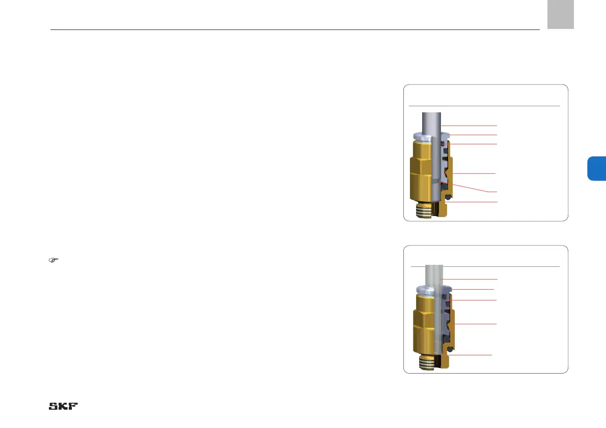
Fig. 41 Quick disconnect cou-
pling for metal tube
Fig. 42 Quick disconnect cou-
pling for plastic tube
Metal tube (1)
Plastic tube (1)
Collet (4)
Collet (4)
First O-ring (2)
First O-ring (2)
Claw groove
Locking claw (5)
Locking claw (5)
Mechanical stop (3)
Mechanical stop (3)
- 83 -
951-230-008-EN
Version 04
EN
 Loading...