Section 04 ENGINE
Sub-Section 03 (599 AND 779 ENGINE TYPES)
04-03-5
RAVE System
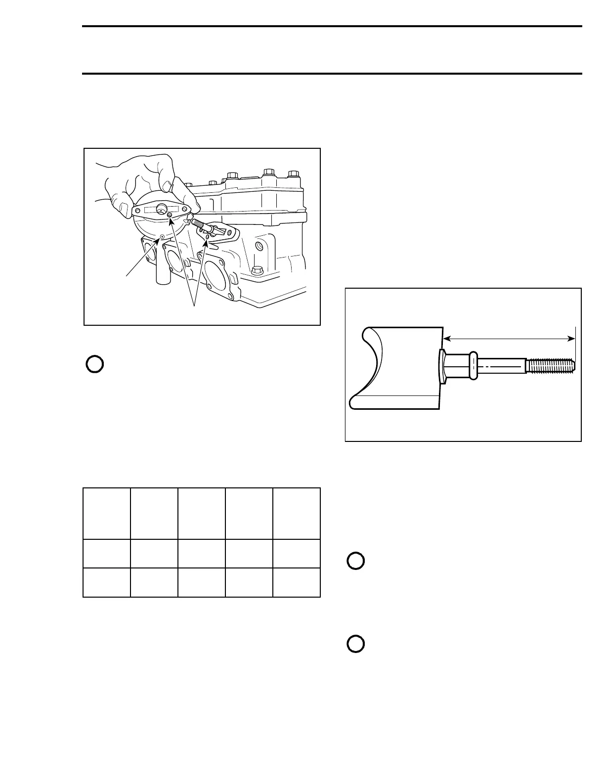
Check valve rod housing and cylinder for clogged
passages.
1. Draining hole
2. Passages
NOTE : Oil dripping from draining hole indi-
cates a loosen clamp or damaged bellows.
10, Valve Rod
Check valve rod for straightness.
15, Bellows
Check for cracked, dried or perforated bellows.
5, Spring
ASSEMBLY
RAVE SYSTEM
779 Only
10,11,12,13,14, Valve Rod, O-ring,
Washer, Distance Nut and Exhaust Valve
Fully screw distance nut, with its notch first, on
valve rod longer threaded portion. Install washer
and apply high temperature threadlocker (P / N
420 8997 88) on threads. Screw valve rod into ex-
haust valve until following distance is respected.
Distance between RAVE valve and valve rod end
is 58 mm + 1 mm (2.283 + .039 in)
779 ENGINE ONLY
A. 58 + 1 mm (2.283 + .039 in)
Back off distance nut to jam the assembly. Install
O-ring. Install exhaust valve assembly in cylinder
with letters TOP facing upwards.
All Engines
Piston and Cylinder
NOTE : Be sure to restore the chamfer
around all cylinder sleeve port openings.
Before inserting piston in cylinder, lubricate the
cylinder with new injection oil or equivalent.
Install ring compressor (P / N 420 8769 74) on pis-
ton assembly.
NOTE : The ring compressor will not fit on
over size pistons.
ENGINE
TYPE
SPRING
P/N
Wire
Dia.
mm
(in)
Free
length
mm
(in)
Spring
Rate
N/mm
(lbs / in)
599
420
2399 40
0.8
(.031)
48.5
(1.91)
0.30
(1.71)
779
420
2399 41
0.8
(.031)
52.5
(2.17)
0.30
(1.71)
A06C0PA
2
1
 Loading...
