Section 04 ENGINE
Sub-Section 05 (CDI SYSTEM)
04-05-8
3.If necessary, adjust by slackening retaining
screws and moving trigger coil toward or away
of protrusion.
4. Retighten screws and recheck air-gap.
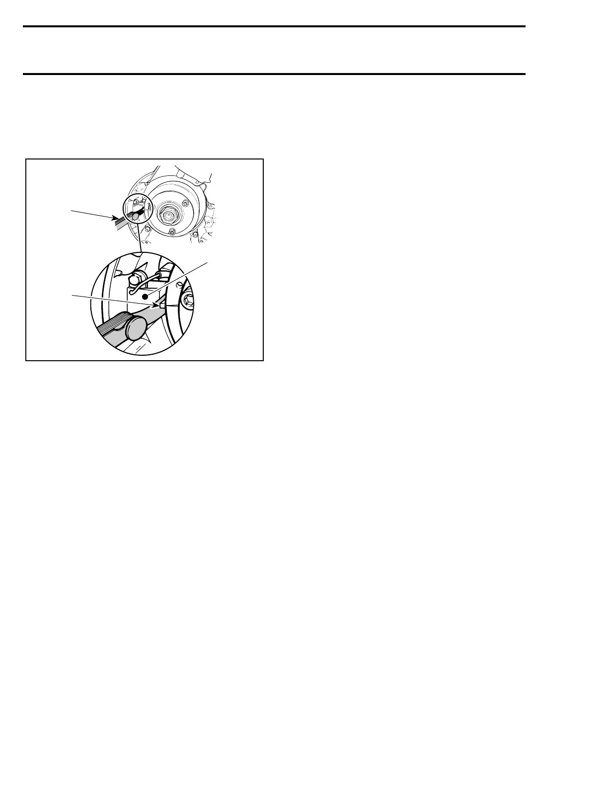
ADJUSTING TRIGGER COIL AIR-GAP
1. Measure at center pole of trigger coil min. 0.45 mm (.018) max.
0.55 mm (.022 in)
2. Trigger coil
3. Flywheel protrusion
1, Armature with Armature Plate
To replace armature :
– Disconnect the 2-wire connector (GREEN and
WHITE wires).
– Disconnect both YELLOW / BLACK and YEL-
LOW wires.
– Remove grommet from crankcase where mag-
neto harness exits magneto housing.
– Remove armature plate retaining screws.
– Remove armature plate with armature and
carefully pull wires.
– Install new parts and other parts removed.
ASSEMBLY
2,3, Magneto Flywheel and Nut
Clean crankshaft extension (taper).
Apply Loctite 242 (blue) on taper.
Position Woodruff key, flywheel and lock washer
on crankshaft.
Clean nut threads and apply Loctite 242 (blue) be-
fore tightening nut to 105 N•m (77 lbf•ft).
At reassembly coat all electric connections with
silicone dielectric grease (P / N 413 7017 00) to
prevent corrosion or moisture penetration.
CAUTION : Do not use silicone “sealant”,
this product will corrode contacts.
Ignition Timing
Check as described in IGNITION TIMING 06-02.
A25E0UA
1
2
3
-
 Loading...
