Section 04 ENGINE
Sub-Section 06 (OIL INJECTION SYSTEM)
04-06-4
OIL PUMP IDENTIFICATION
7, Pump Lever
Different engines need different pumps. Oil
pumps are identified by their levers.
CAUTION : Always mount proper pump
on engine.
NOTE : The following procedures can be
done without removing the engine from
chassis.
CLEANING
Clean all metal components in a non-ferrous met-
al cleaner.
DISASSEMBLY
NOTE : Some oil pump components are not
available as single parts.
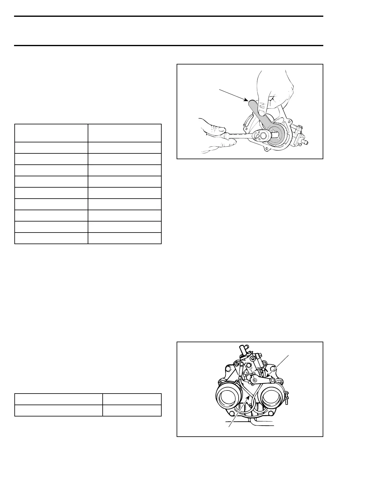
1,2, Gear Retaining Nut and Oil Pump
Gear
To remove gear retaining nut, first extract the nee-
dle roller with pliers then lock gear in place using
one of the following gear holder :
TYPICAL
ASSEMBLY
2, Oil Pump Gear
At gear assembly, apply a light coat of low tem-
perature grease (P / N 413 7061 00) on gear teeth.
4, Needle Roller (Fan Cooled Engine
Only)
The needle roller must be engaged as deep as
possible in the pump mounting flange.
5,6, Spring Clip and Clamp
Always check for spring clips and clamps tight-
ness.
3, Screw
Torque to 9 N•m (80 lbf•in).
CAUTION : Whenever oil injection lines
are removed, always make the routing as
shown.
1. Oil pump lever
2. Twist oil lines
ENGINE TYPE
OIL PUMP
IDENTIFICATION
454 P3
503 E3
583 Formula STX / Z N3
583 MX Z N6
583 Summit N2
599 04
670 Formula SS N2
670 Summit N6
779 03
ENGINE TYPE TOOL P / N
454 / 583 / 599 / 670 / 779 420 2779 05
'
'
A00C17A
420 2779 05
 Loading...
