Section 04 ENGINE
Sub-Section 07 (AXIAL FAN COOLING SYSTEM)
04-07-3
9, Fan Shaft
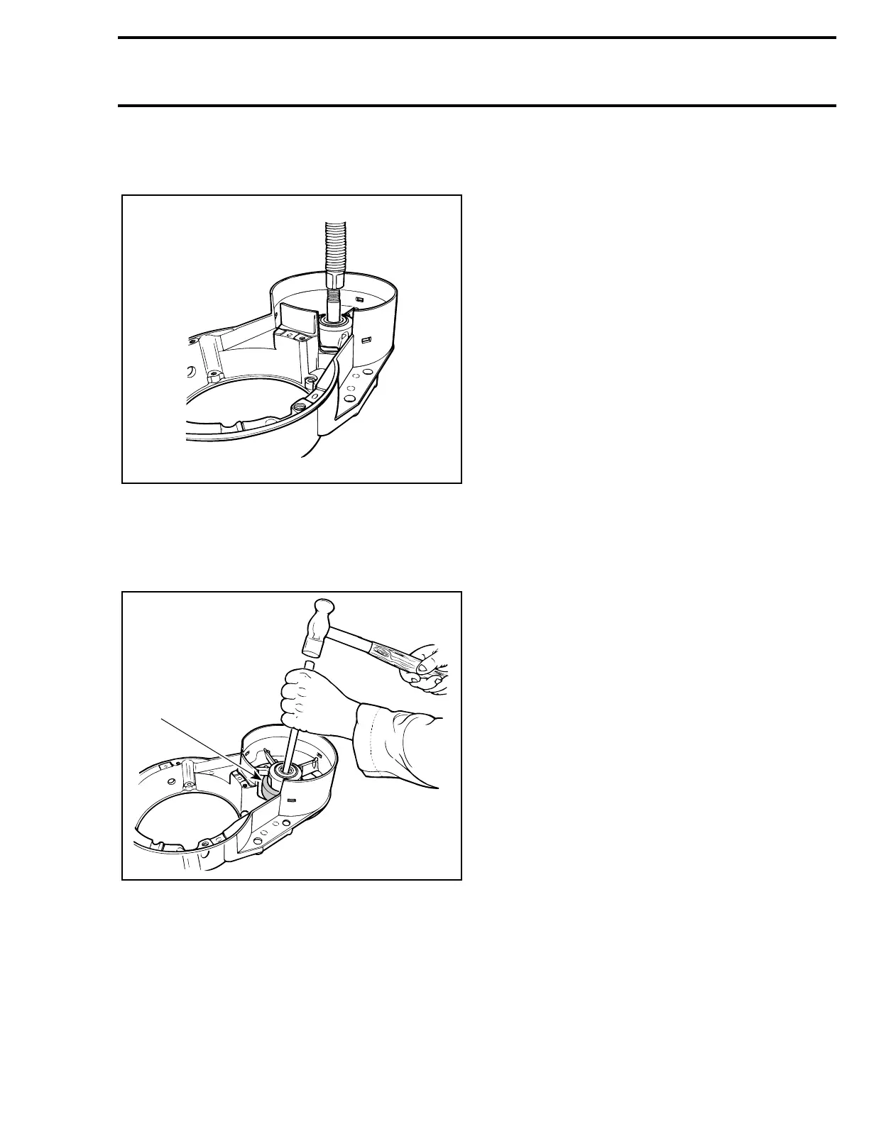
Using a press, drive the fan shaft out.
10,12, Bearing and Fan Housing
Support fan housing with a ring. With a punch,
working all around bearing inner race, drive bear-
ing out of fan housing. Keep shims for installation.
1. Ring supporting fan housing
10,11, Bearing and Circlip
Remove circlip then remaining bearing.
To install, press one bearing in place then install
circlip and shims. Press the other bearing from op-
posite side until it is flush with housing. Press fan
shaft from engine side of fan housing. Check for
free rolling action.
1,2,3, Screw, Loctite 242 (Blue) and
Cylinder Cowl
At assembly, apply a light coat of Loctite 242
(blue) on threads. It should be noted that to cor-
rectly remove a threadlocked screw, it is first nec-
essary to slightly tap on screw head to break
threadlocker bond. This will eliminate the possibil-
ity of screw breakage.
6,7,8, Rivet, Washer and Air Duct
Check for damage or permanent deformation.
Air duct can be removed by drilling out rivets.
CAUTION : At reassembly, use only
closed end rivets to avoid rivet ends from
falling into magneto.
Install washer over air duct.
On all engines, check fit of engine air duct with
hood air duct. Adjust hood as necessary.
4,5, Cylinder Cowl
A gasket must be placed on both sides (inner and
outer) of intake and exhaust holes of cylinder
cowl.
18, Fan Protector
Reinstall properly.
WARNING : Always reinstall fan protector
after servicing.
A23C06A
A23C07A
1
 Loading...
