Section 04 ENGINE
Sub-Section 09 (ROTARY VALVE, COOLANT PUMP AND RESERVOIR)
04-09-7
– Turning crankshaft, bring MAGneto side piston
to Top Dead Center as done before with a
crankcase having a ridge.
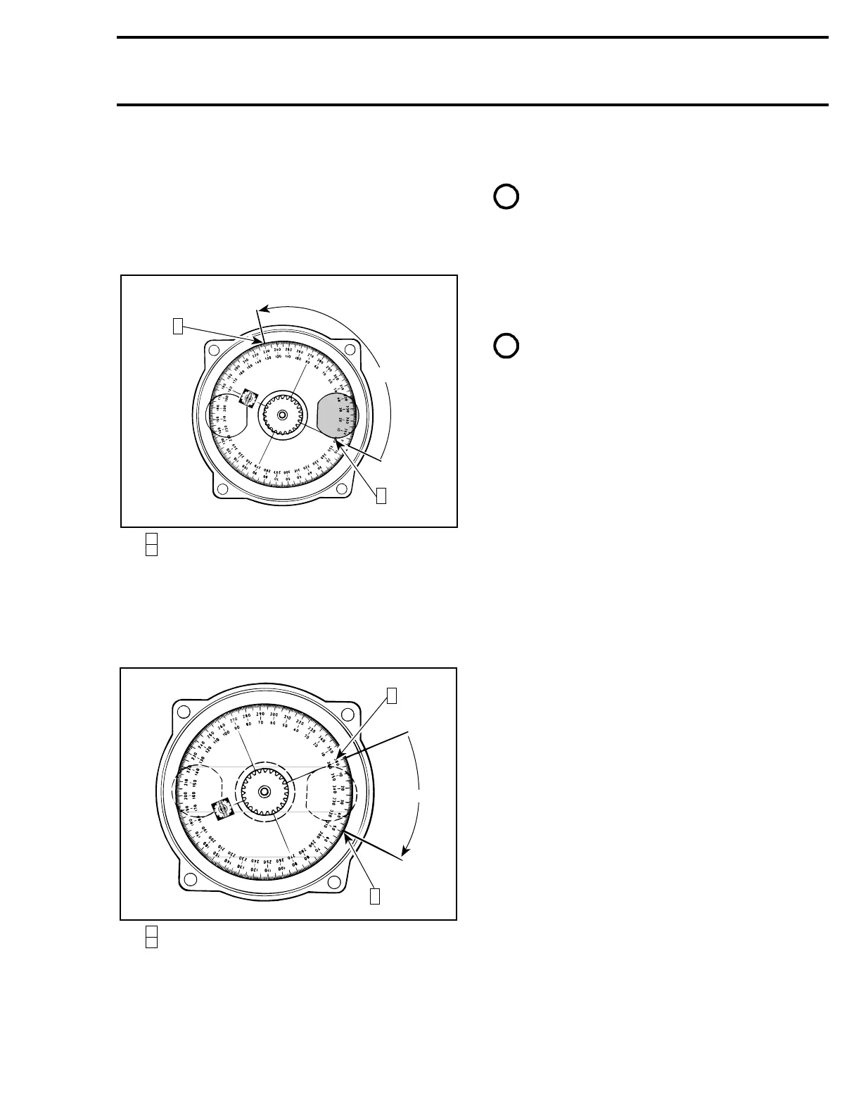
– For opening mark, first align 360° line of degree
wheel with BOTTOM of MAGneto side inlet
port. Then, find 132° line on degree wheel and
mark crankcase at this point.
Step : Align 360° line of degree wheel here
Step : Find 132° on degree wheel and mark here
1. Opening mark
2. Bottom of MAGneto inlet port
–For closing mark, first align 360° line of degree
wheel with TOP of MAGneto side inlet port.
Then, find 52° line on degree wheel and mark
crankcase at this point.
Step : Align 360° line of degree wheel here
Step : Find 52° on degree wheel and mark here
1. Top of MAGneto inlet port
2. Closing mark
– Position rotary valve on shaft splines to have
edges as close as possible to marks.
NOTE : Rotary valve is asymmetrical. There-
fore, try turning it inside out then reinstall on
splines to determine best installation position.
Apply injection oil on rotary valve before closing
rotary valve cover.
To Time Rotary Valve Exactly to
Specifications
NOTE : If desynchronization (out of spec.) is
unknown, install rotary valve to determinate
it before proceeding with the following.
First Method
Turn crankshaft to bring MAG piston to TDC.
Scribed marks of crankshaft and upper crankcase
must aligned. These marks were scribed while
determinating desynchronization.
Install brass gear on rotary valve shaft with its
marked spline 4 positions (splines) away for one
degree of desynchronization. Turn in the opposite
direction of desynchronization. For instance, a ro-
tary valve is retarded by 2.5°, turn brass gear by
10 splines counterclockwise.
Second Method
Turn crankshaft to bring MAG piston to TDC.
Scribed marks of crankshaft and upper crankcase
must aligned. These marks were scribed while
determinating desynchronization.
For each degree of desynchronization, rotary
valve shaft should be turned in the opposite direc-
tion by about 5 splines on the rotary valve gear.
Note position of rotary valve gear mark when
brass gear disengage worm gear of crankshaft at
removal of rotary valve shaft. From this position,
turn shaft accordingly then reinstall.
For instance, take a valve advanced by 2°.
132°
F01D2JA
1
2
1
2
1
2
52°
F01D2KA
1
1
2
2
1
2
 Loading...
