Section 04 ENGINE
Sub-Section 11 (CARBURETOR AND FUEL PUMP)
04-11-6
CARBURETOR FLOAT LEVEL
ADJUSTMENT
9,10, Float Arm and Float Arm Pin
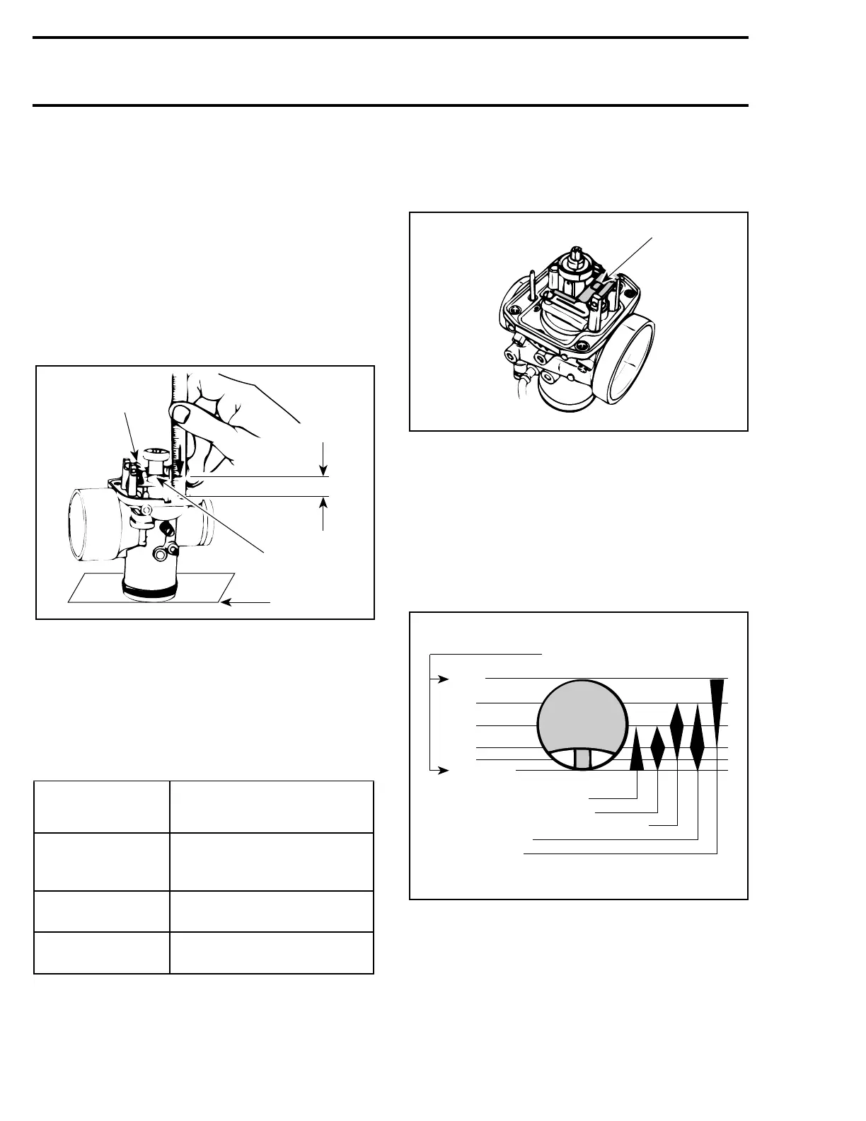
Correct fuel level in float chamber is vital toward
maximum engine efficiency. To check for correct
float level proceed as follows :
– Remove float bowl and gasket from carburetor.
– With carburetor chamber upside-down on a lev-
el surface, measure height H between bowl
seat and top edge of float arm.
TYPICAL
1. Contact tab
2. Float arm
3. Level surface
4. H
On TM 38, do not turn carburetor up side down.
Measure float arm height when it just touches
needle valve without moving it.
Float arm height dimensions :
To Adjust Height H :
– Bend the contact tab of float arm until the spec-
ified height is reached.
1. Contact tab
The illustration below shows which part of the
carburetor begins and to stops to function at dif-
ferent throttle slide openings.
Note that the wider part of symbol corresponds to
the opening mostly affected. For instance, throt-
tle slide cut-away begins to function at close posi-
tion but it is most effective at 1/4 opening and
decreases up to 1/2 opening.
NOTE : For fine tuning refer to TECHNICAL
DATA section 10 and to SPARK PLUG 06-03.
NOTE : For high altitude regions, the
High
Altitude Technical Data
(P / N 484 0624 00
and 484 0545 00 for binder) gives information
about calibration according to altitude and temper-
ature.
CARBURETOR
MODEL
FLOAT HEIGHT H
± 1 mm (± .040 in)
VM 32-269
VM 34-469
VM 34-470
23.9 (.941)
VM 38
VM 40
18.1 (.713)
VM 38 (Summit)
VM 40 (Summit)
19.6 (.772)
A00C02A
A
1
2
3
A00C03A
1
Throttle slide openings
Wide
open
3/4
1/2
1/4
1/8
Close
Pilot jet and air screw13,6,
Throttle slide cut-away5,
Needle taper and needle position3,
Needle jet14,
Main jet8,
A00C04A
'
'
 Loading...
