Section 05 TRANSMISSION
Sub-Section 02 (DRIVE PULLEY)
05-02-10
This adjustable drive pulley allows setting maxi-
mum engine RPM in the vehicle to maintain max-
imum power.
Calibration screws should be adjusted so that ac-
tual maximum engine RPM in vehicle matches
with the maximum horsepower RPM given in
TECHNICAL DATA 10.
NOTE : Use precision digital tachometer for
engine RPM adjustment.
NOTE : The adjustment has an effect on
high RPM only.
To adjust, modify ramp end position by turning cal-
ibration screws.
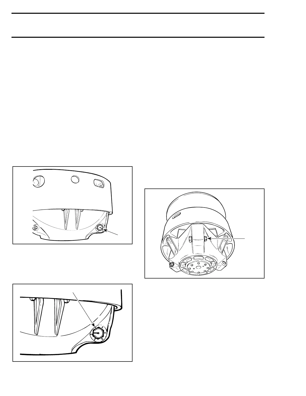
26,28,29, Calibration Screw, Locking
Nut and Governor Cup
Calibration screw has a notch on top of its head.
1. Notch
Governor cup has 6 positions numbered 2 to 6.
Note that in position 1 the number is substituted
by a dot (due to its location on casting).
See TECHNICAL DATA 10 for original setting.
1. Position 1 (not numbered)
Each number modifies maximum engine RPM by
about 200 RPM.
Lower numbers decrease engine RPM in steps of
200 RPM and higher numbers increase it in steps
of 200 RPM.
Example :
Calibration screw is set at position 4 and is
changed to position 6. So maximum engine RPM
is increased of 400 RPM.
To Adjust :
Just loosen locking nut enough to pull calibration
screw partially out and adjust to desired position.
Do not completely remove the locking nut. Torque
locking nuts to 10 N•m (89 lbf•in).
CAUTION : Do not completely remove
calibration screw or its inside washer will
fall off.
CAUTION : Always adjust all 3 calibration
screws and make sure they are all set at
the same number.
1. Loosen just enough to permit rotating of calibrate screw
'
'
A16D0FA
1
A16D0HA
1
 Loading...
