Section 06 ELECTRICAL
Sub-Section 06 (TESTING PROCEDURE)
06-06-10
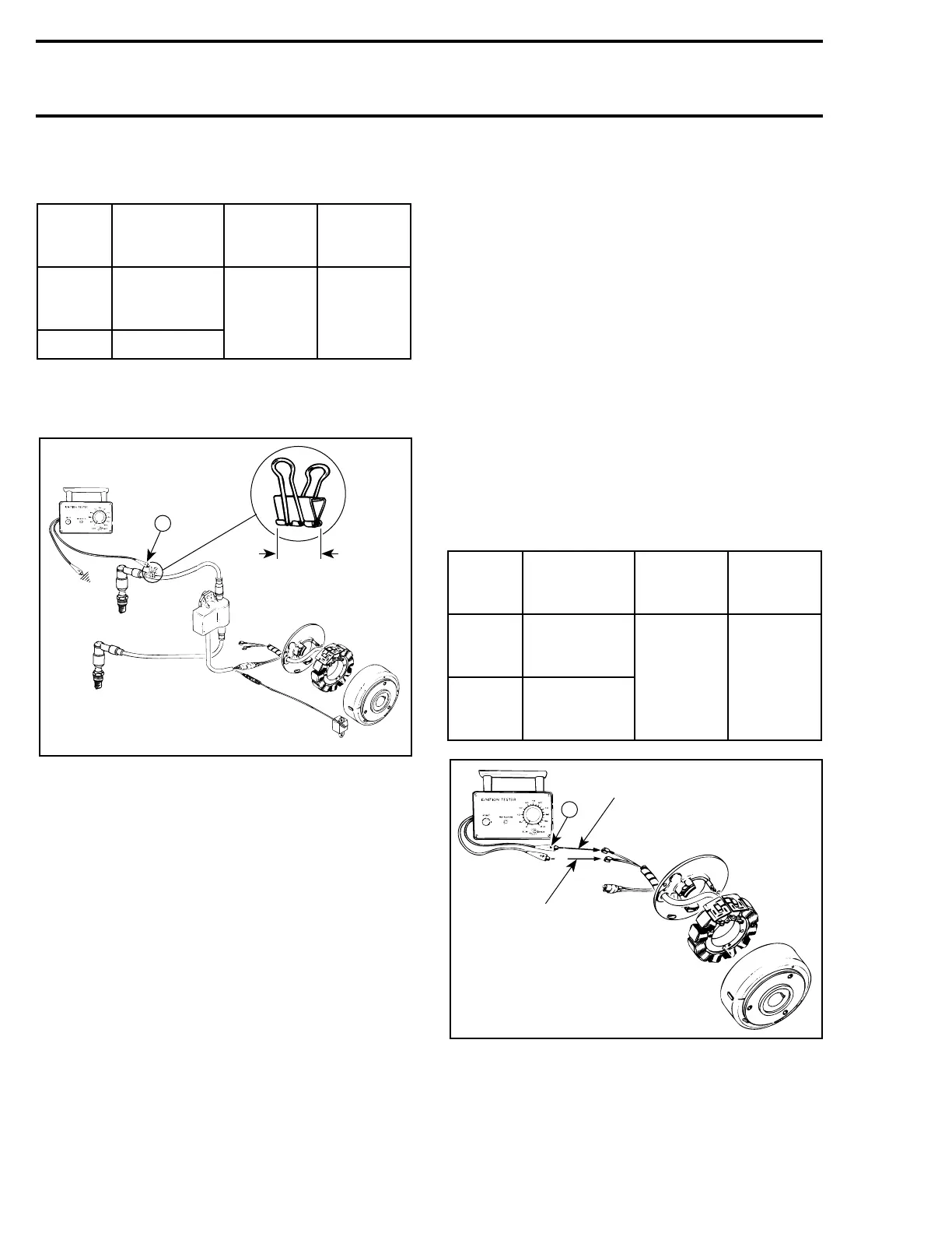
2. Connect tester wires then set switch and dial
as follows :
NOTE : Different reading occurs if N tester
wire is connected to PTO side spark plug ca-
ble.
1. Engine ground
2. MAG side
A. 20 mm (3/4 in)
3. Crank engine and observe indicator.
NOTE : If engine starts, allow it to idle while
observing indicator. Then, shut engine off.
4. Push reset button and repeat step 3 twice.
Results :
a. Indicator lamp lights : Ignition system is
OK.
b. Indicator lamp does not light on one or
both cylinder : The problem is a faulty igni-
tion coil / module.
IGNITION MODULE
Ignition module can not be tested with the Bom-
bardier ignition tester. When other components
test good, the module is probably faulty. Try a new
module.
LIGHTING GENERATOR COIL
OUTPUT
NOTE : The lighting generator coil is not part
of the ignition system. It is a separate sys-
tem that supplies current to the lighting system
and AC-powered devices. However it can be test-
ed with the same tester.
1. Disconnect wiring harness junction block at en-
gine (the one with YELLOW and YELLOW
wires).
2. Connect tester wires then set switch and dial
as follows :
3. Crank engine and observe indicator.
4. Push reset button and repeat step 3 twice.
Tester
wires
Component
wires
Tester
switch
position
Tester
dial
position
N
Test adapter
(paper clip) on
spark plug cable
LOW 80
P Engine ground
'
A17E0WA
N
A
2
1
'
Tester
wires
Component
wires
Tester
switch
position
Tester
dial
position
N
YELLOW
wire of
magneto harness
LOW 80
P
YELLOW
wire of
magneto harness
'
 Loading...
