Section 06 ELECTRICAL
Sub-Section 06 (TESTING PROCEDURE)
06-06-12
RESISTANCE MEASUREMENTS
As an alternate method, magneto system compo-
nents can be checked with a digital ohmmeter.
NOTE : All resistance measurements must
be performed with parts at room tempera-
ture (approx. 20°C (68°F)). Temperature greatly af-
fects resistance measurements.
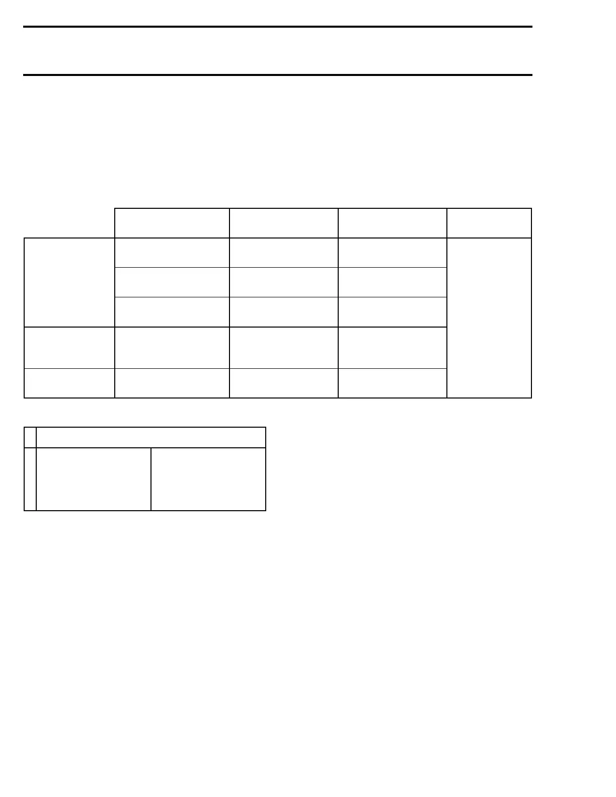
Disconnect connector at ignition coil and magneto
junction. Measure resistance between each ter-
minal. Refer to the following table for values and
wire colors.
NOTE : An ignition coil with good resistance
measurement can still be faulty. Voltage leak
can occur at high voltage level which is not detect-
able with an ohmmeter.
➀
: The primary winding of ignition coil can not be measures because there is no external connection.
'
'
PART
NAME
WIRE COLOR*
RESISTANCE
OHM
REMARKS
MAGNETO
Trigger
coil
RD with
engine ground
140 - 180
No display
change means
open circuit.
Ignition
generator coil
WH with GN 230 - 330
Lighting
generator coil
YL with YL 0.23 - 0.28
IGNITION
COIL
Secondary winding
➀
(spark plug
cap removed)
End of each high
tension wire
5.1 - 6.3 K
(5100 - 6300)
Display showing
zero (0) means
short circuit.
SPARK PLUG
CAP
Spark plug
cap
— 4.5 - 5.5 K
*
COLOR CODE
BK — BLACK
WH — WHITE
RD — RED
BL — BLUE
YL — YELLOW
GN—GREEN
GY — GREY
VI — VIOLET
OR — ORANGE
BR — BROWN
 Loading...
