Section 07 REAR SUSPENSION
Sub-Section 01 (SUSPENSION SC-10 HIGH PERFORMANCE, CROSS-COUNTRY AND
07-01-5
6, Screw
Remove both screws retaining front arm to tun-
nel.
Remove suspension.
DISASSEMBLY AND ASSEMBLY
Inspect track throughly before reinstalling suspen-
sion. Refer to TRACK 07-05.
1, Rear Arm
At installation, rear arm stroke limiter must be on
rear side.
1. Stroke limiter on rear side
8,9, Pivot Arm and Flat Washer
At installation pivot arm grease fitting must face
rearward.
10, Outer Bushing
At installation, hole must face adjustment screw.
11, Axle
Note position of axles at disassembly. Axles with
a paint stripe serve as idler wheel axles. These are
more precise than those used as pivot axles. Idler
wheel axles can be used as pivot axles but the
opposite is not true.
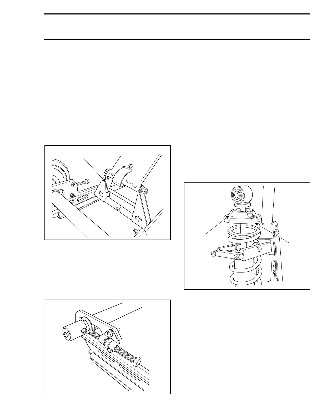
12,13,14, Front Shock, Spring Stopper
and Cap
Use shock spring remover (P / N 529 0271 00) in
a vise. Mount shock in it and turn shock so that
spring coils matched spring compressor.
Close and lock bar. Adjust handle horizontal by
changing position of clevis pin.
Push down on handle until it locks. Remove
spring stopper and cap then release handle.
At installation, cap opening must be 180° from
spring stopper opening.
1. Cap opening
2. Spring stopper opening
20, Stopper Strap
Inspect strap for wear or cracks, bolt and nut for
tightness. If loose, inspect hole for deformation.
Replace as required. Make sure it is attached
through the 2
nd
hole from the end on all MX Z and
to the 1
st
hole on Formula Z / SS. Torque nut to 11
N•m (97 lbf•in).
A03F13A
1
 Loading...
