Section 07 REAR SUSPENSION
Sub-Section 03 (IMPROVED C-7 SUSPENSION)
03-03-3
Position notch in outer spacer forward and inward
onto the rear axle.
10,12,13,14,15, Screw
Clean all screw threads and axle hole threads. Pri-
or to assembly, apply low temperature grease (P /
N 413 7061 00) on axles and Loctite 271 (P / N
413 7074 00) on screw threads.
11, Elastic Stop Nut
Inspect for damage and replace as required.
INSTALLATION
CAUTION : Close fuel shut-off valve(s) be-
fore lifting vehicle.
Lift rear of vehicle off the ground about 850 mm
(33-1/2 in). Install assembled suspension into
track with front portion first. Insert rear portion of
suspension into track.
Bolt suspension to tunnel following sequence and
torque values as follows.
TYPICAL
A. 48 N•m (35 lbf•ft)
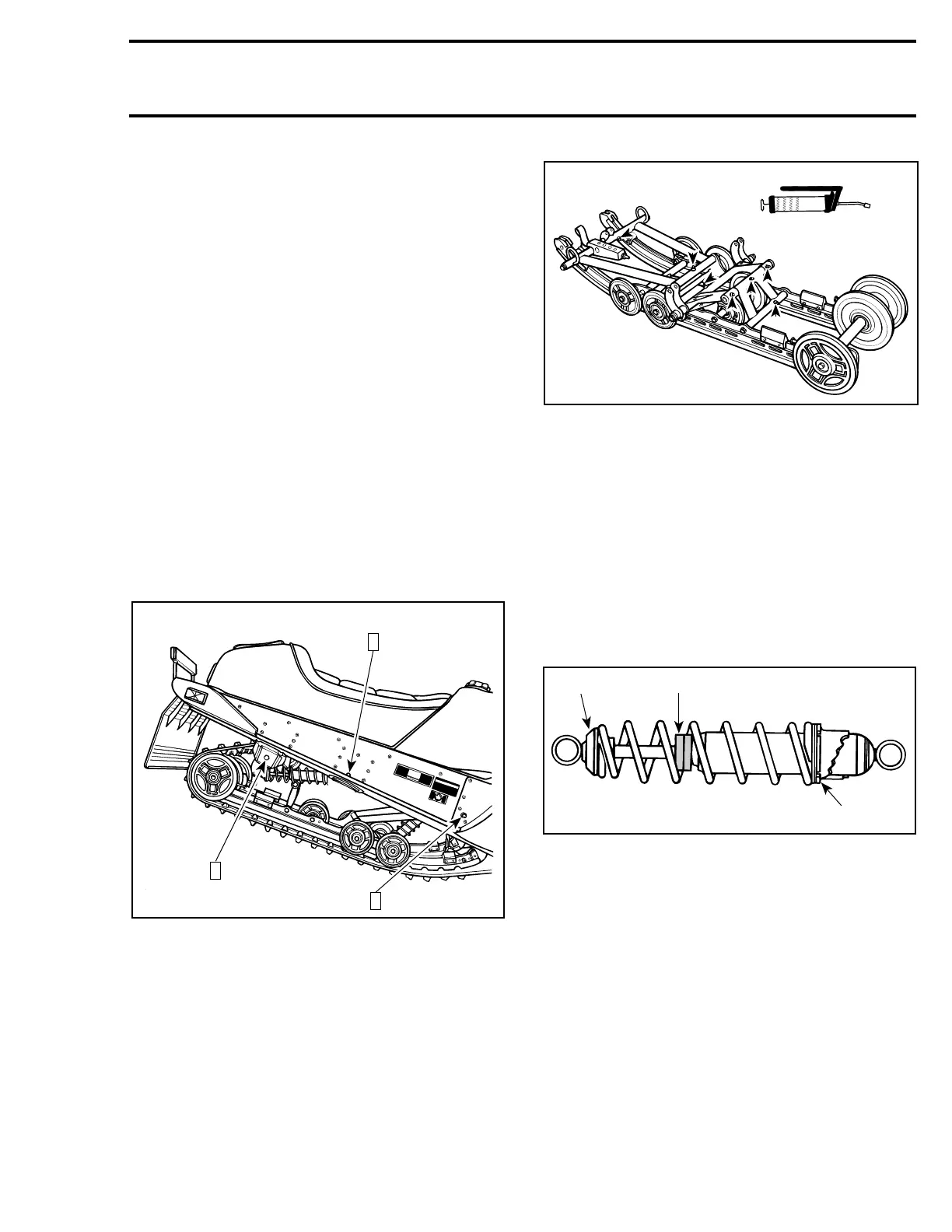
16, Grease Fitting
Lubricate until grease appears at joints using low
temperature grease (P / N 412 7061 00) :
– Front arm : upper and lower axles.
– Rear arm : upper and lower axles.
– Rear shackle.
NOTE : There are 7 lubrication points.
TYPICMAL
SHOCK ABSORBER SPRING
REPLACEMENT
WARNING : Do not attempt to dismantle a
shock absorber spring without using the
proper spring compressor. Do not apply heat
or flame to the rear gas pressurized shocks.
NOTE : Before attempting to compress the
spring, push the rubber bumper against the
shock body and place the adjuster ring at its low-
est position.
TYPICAL
1. Spring collar
2. Bumper against shock body
3. Lowest position
Install spring compressor (P / N 529 0271 00) in a
vise. Mount shock in it and turn shock so that
spring coils matched spring compressor.
Close and lock bar. Adjust handle horizontal by
changing position of clevis pin.
Push down on handle until it locks. Remove
spring stopper then release handle.
A06F05B
3
A
2
A
1
A
'
A06F08A
 Loading...
