Section 07 REAR SUSPENSION
Sub-Section 05 (TRACK)
07-05-1
TRACK 5
TRACK TYPE APPLICATION
Refer to TECHNICAL DATA section10.
GENERAL
This section gives guidelines for track removal.
Some components require more detailed disas-
sembly procedures. In these particular cases, re-
fer to the pertaining section in this manual.
INSPECTION
Visually inspect track for :
– cuts and abnormal wear
– broken rods
– broken or missing track cleats
If track is damaged or rods are broken, replace
track. For damaged or missing cleats, replace by
new ones, using cleat remover (P / N 529 0287
00). Use small-cleat installer (P / N 529 0085 00).
WARNING : Do not operate a snowmobile
with a cut, torn or damaged track.
REMOVAL
S Series and F Series
Remove the following parts :
– speedometer cable
– muffler
– chaincase cover
– suspension
– drive axle seal
– end bearing housing
– sprockets and chain
– drive axle (toward end bearing housing)
– track
Skandic WT
Remove the following parts :
– rear suspension
– muffler
– RH drive axle end bearing
– angle drive and square pin
Move transmission sideway. Do not remove
brake mechanism nor driven pulley. Refer to
SKANDIC WT SUSPENSION 07-02.
Remove drive axle then track.
INSTALLATION
All Models
Reverse the removal procedure.
NOTE : When installing the track, respect
rotation direction indicated by an arrow on
track thread.
Check sprocket / track alignment as described in
DRIVE AXLE 07-04.
Track Tension and Alignment
Track tension and alignment are inter-related. Do
not adjust one without checking the other. Track
tension procedure must be carried out prior to
track alignment.
Tension
Lift the rear of vehicle and support with a mechan-
ical stand. Allow the slide to extend normally.
Check the gap half-way between front and rear
idler wheels. Measure between slider shoe and
bottom inside of track.
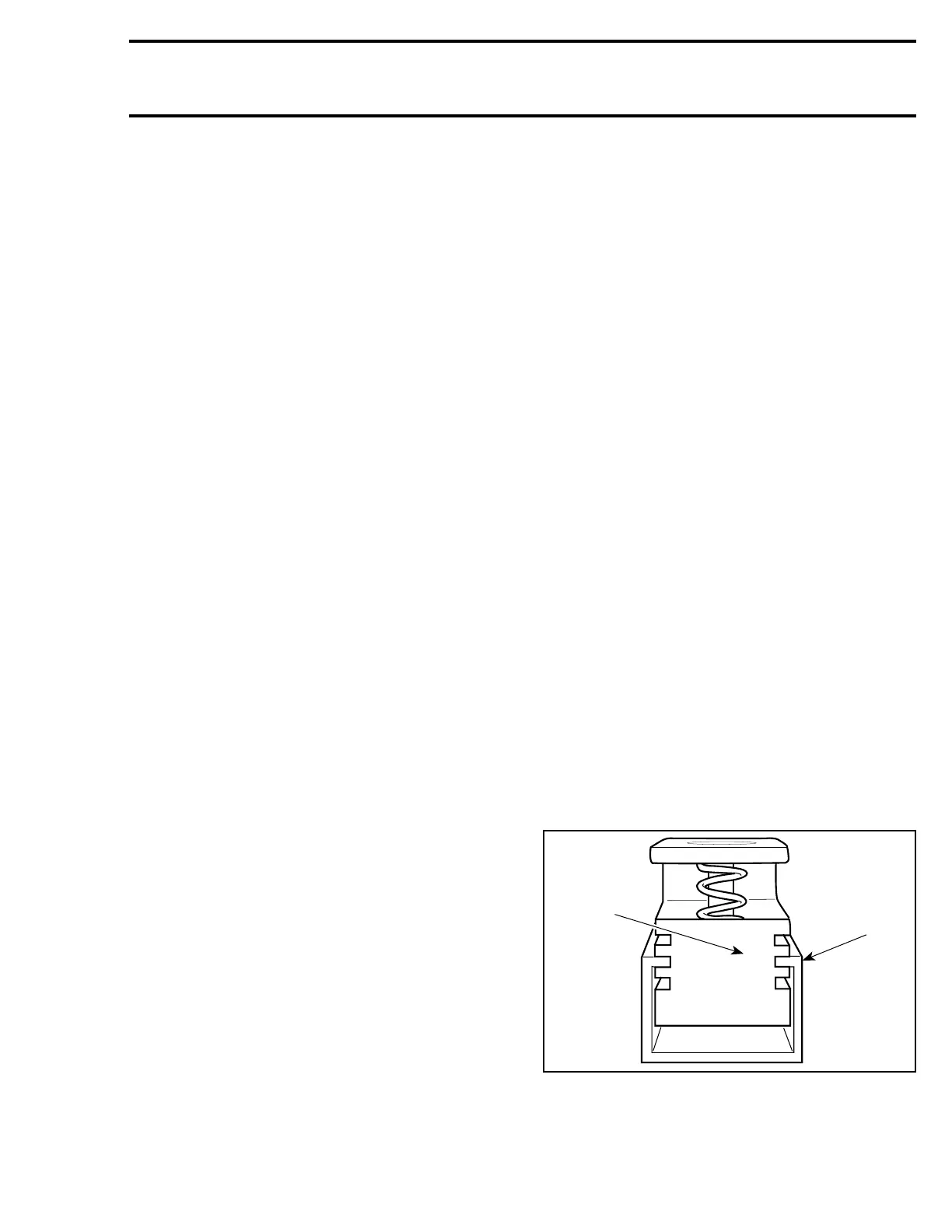
When using the track tension gauge (P / N 529
0215 00), slide U shape extrusion to proper de-
flection.
1. Example 45 mm
2. Extrusion
;
 Loading...
