Section 04 ENGINE
Sub-Section 01 (503 ENGINE TYPE)
04-01-8
NOTE : Engine must be removed from
chassis to perform the following proce-
dures.
CLEANING
Discard all seals, gaskets and O-rings.
Clean all metal components in a non-ferrous met-
al cleaner. Use gasket remover (P / N 413 7085
00) accordingly.
10, Loctite 242
Remove all trace of Loctite from crankshaft taper.
Remove old sealant from crankcase mating sur-
faces with Bombardier gasket remover (P / N 413
7085 00).
CAUTION : Never use a sharp object to
scrape away old sealant as score marks
incurred are detrimental to crankcase sealing.
DISASSEMBLY
General
To remove drive pulley, refer to DRIVE PULLEY
05-02.
To remove magneto, refer to CDI MAGNETO 04-
04.
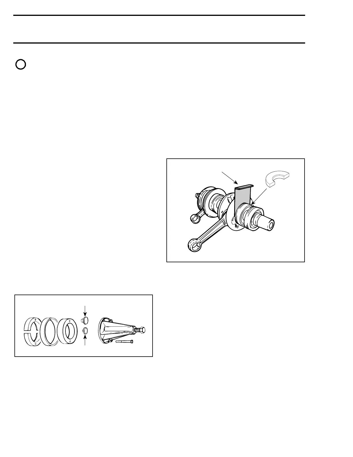
4, Ball Bearing
To remove bearings from crankshaft, use a pro-
tective cap and a special puller, as illustrated.
1. PTO side
2. MAG side
INSPECTION
Refer to ENGINE DIMENSIONS MEASUREMENT
04-03.
ASSEMBLY
3,4, Anti-seize Lubricant and Ball
Bearing
Smear anti-seize lubricant (P / N 413 7010 00) on
part of crankshaft where bearing fits.
PTO Side Bearings
To check proper clearance between bearing and
counterweight, use feeler gauge (P / N 420 8766
20).
Mount second bearing with distance gauge (P / N
420 8768 24) for proper positioning.
1. Feeler gauge
2. Distance gauge
Prior to installation, place bearings into an oil con-
tainer filled with oil heated to 75°C (167°F).
This will expand bearings and ease installation. In-
stall bearings with groove as per exploded view.
Bearings are pressed on crankshaft until they rest
against radius. These radius maintain the gap
needed for bearings lubrication.
2, Seal
At seal assembly, apply a light coat of lithium
grease on seal lip.
For bearing lubrication purpose, a gap of 1.0 mm
(.040 in) must be maintained between seals and
bearings.
When installing plain oil seals (seal without locat-
ing ring or without spacing legs), ensure to main-
tain 1.0 mm (.040 in) gap.
-
A00C38A
1
2
A00C46A
1
2
 Loading...
