Section 04 ENGINE
Sub-Section 02 (454, 583 AND 670 ENGINE TYPES)
04-02-2
REMOVAL FROM VEHICLE
Disconnect or remove the following from vehicle.
– air intake silencer
– belt guard and drive belt
– drive pulley
– carburetors and throttle cable at oil injection
pump
– impulse line, oil supply line and rotary valve
shaft lubrication hoses then plug all these hoses
– ignition coils and ignition module
– temperature sensor connector, 4 circuit con-
nector, 3 circuit connector and black / yellow
wire
– drain the cooling system and disconnect hoses
from the engine. Refer to COOLING SYSTEM
04-08
– 4 screws retaining support to frame
ENGINE SUPPORT AND
MUFFLER DISASSEMBLY AND
ASSEMBLY
1,2, Manifold Screw and Engine
Support Screw
Torque the engine support screws to 48 N•m (35
lbf•ft).
Torque the manifold screws to 23 N•m (17 lbf•ft).
INSTALLATION ON VEHICLE
To install engine on vehicle, reverse removal pro-
cedure. However, pay attention to the following :
– Check tightness of engine rubber mount nuts.
Torque to 25 N•m (18 lbf•ft).
– After throttle cable installation, check carbure-
tor maximum throttle opening and oil injection
pump adjustment.
– Check pulley alignment and drive belt tension.
CAUTION : A red dot is printed on one
carburetor and on oil pump mounting
flange. Match the marked carburetor to the
side marked on the oil pump mounting flange
(magneto side). This is required because of the
different jettings.
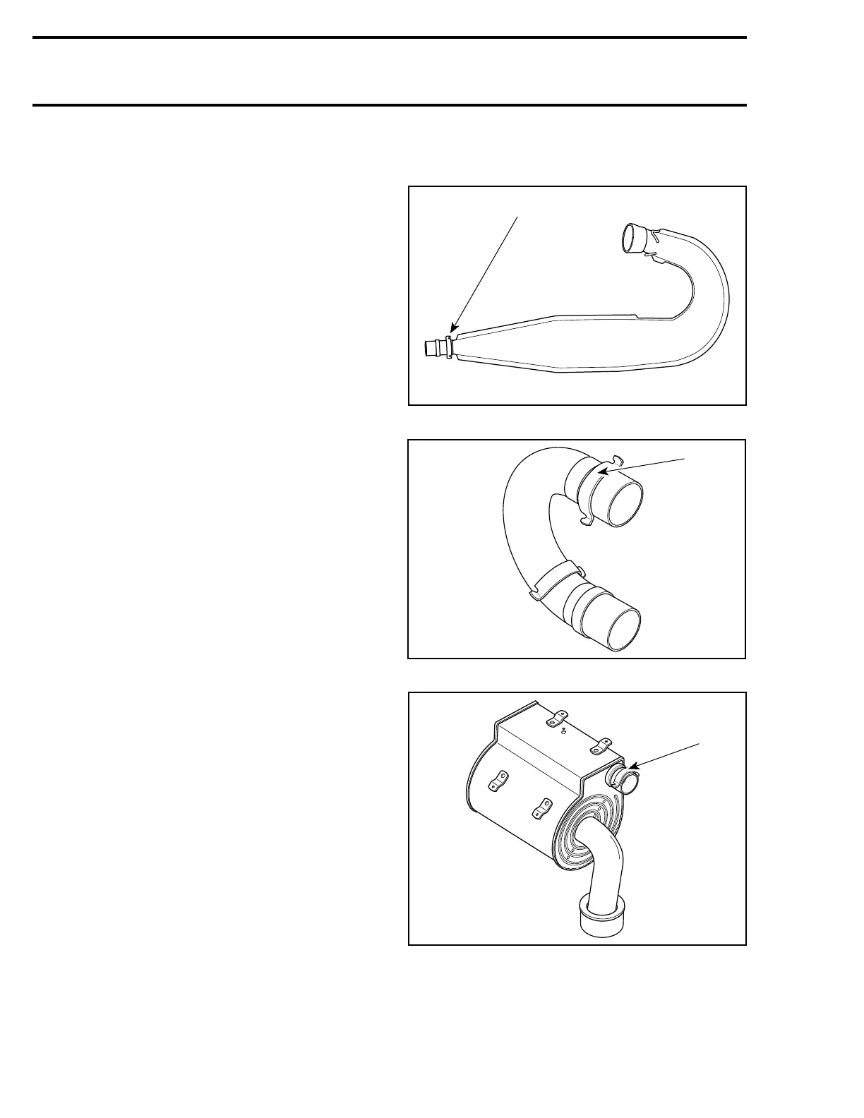
3,4,5, Tuned Pipe, Tail Pipe and Muffler
These parts are identified on welded hook.
Second number sequence of P / N is stamped on
part.
1. Example : 0392 for 514 0392 00
1. Number sequence
1. Number sequence
– Should a light exhaust leak be experienced at
any ball joints, Dow Corning sealer no. 736 RTV
(P / N 413 7092 00) can be used.
-
X
X
X
X
A06C1JA
1
X
X
X
X
A06C1KA
1
 Loading...
