Section 04 ENGINE
Sub-Section 02 (454, 583 AND 670 ENGINE TYPES)
04-02-7
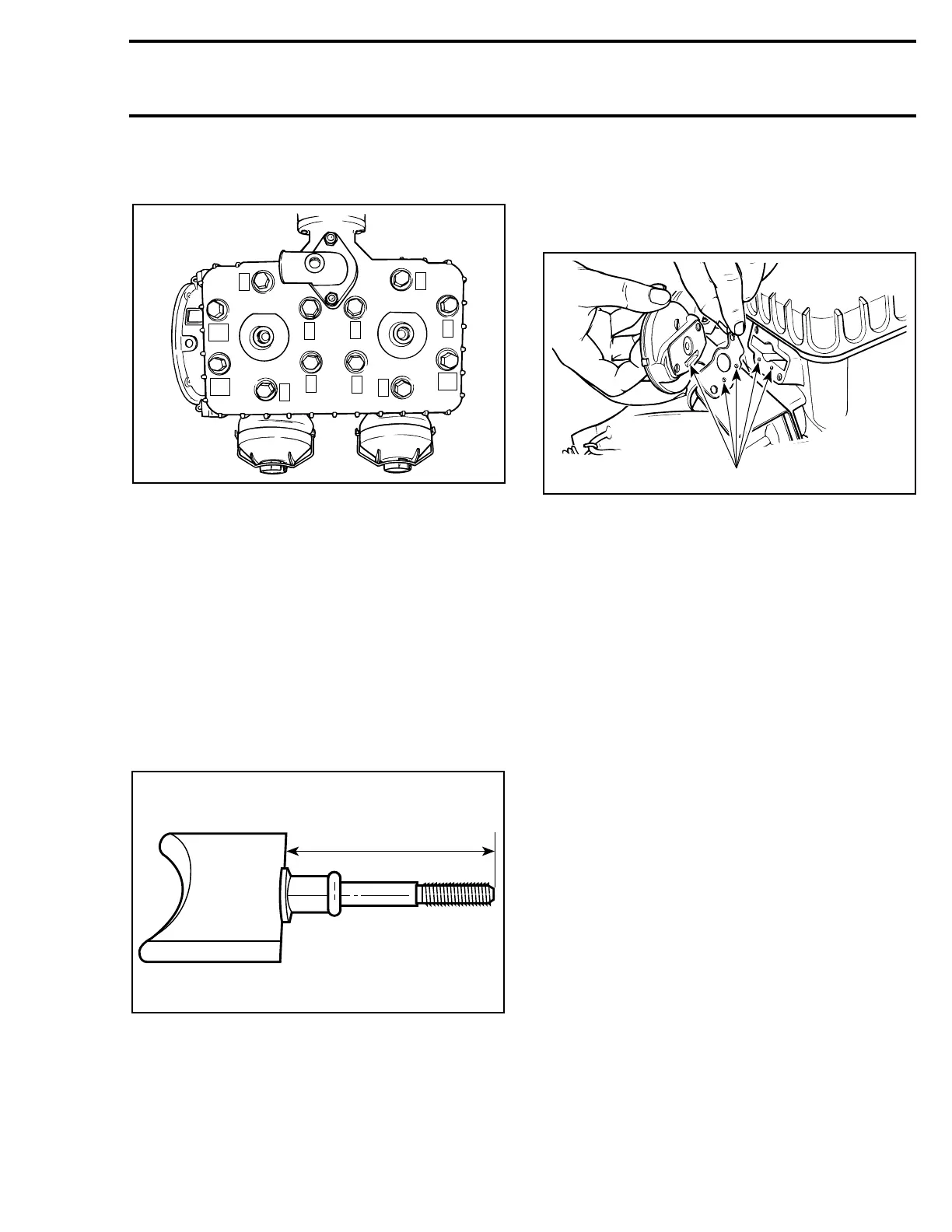
Torque cylinder head screws following illustrated
sequence. Longer screws go on intake side.
1, Nut
Torque nuts to 10 N•m (90 lbf•in).
RAVE SYSTEM
15,16,17,18,19,20, Valve Rod,
Threadlocker, O-ring, Washer, Distance
Nut and Exhaust Valve
Fully screw distance nut, with its notch first, on
valve rod longer threaded portion. Install washer
and apply high temperature threadlocker (P / N
420 8997 88) on threads. Screw valve rod into ex-
haust valve until following distance is respected.
A. 583 engine type = 63
-1
mm (2.480
-.039
in)
Back off distance nut to jam the assembly. Install
O-ring. Install exhaust valve assembly in cylinder
with its cut-away downward (see illustration at re-
moval).
11,12,13,14, Cylindrical Screw, Lock
Washer, Valve Rod Housing and Gasket
Install gasket and valve rod housing with their pas-
sages toward bottom.
1. Passages
Torque cylindrical screws to 10 N•m (90 lbf•in).
Check free sliding action of valve assembly.
7,8,9,10, Valve Piston, Clamp 50 mm,
Bellows and Clamp 21 mm
Install bellows over valve rod housing groove and
secure with a clamp.
Screw by hand valve piston on valve rod until it
bottoms.
Secure bellows to valve piston with a clamp.
3,4,5,6, Spring Clip, Adjustment Screw
Cover and Spring
Install spring, cover and spring clip. Turn adjust-
ment screw by hand until it bottoms.
A24C0JA
5
11
1
12
6
4
3
2
7
9
8
10
A24C0SA
A
 Loading...
